Due to a ransomware attack, the wiki was reverted to a July 2022 version. . We apologize for the lack of a more recent valid backup.
...
(2) Host (.14) at Orlando (ORLD) is selected:

(3) "Create Host-to-Host Intent Flow" action button pressed (on Detail Panel):
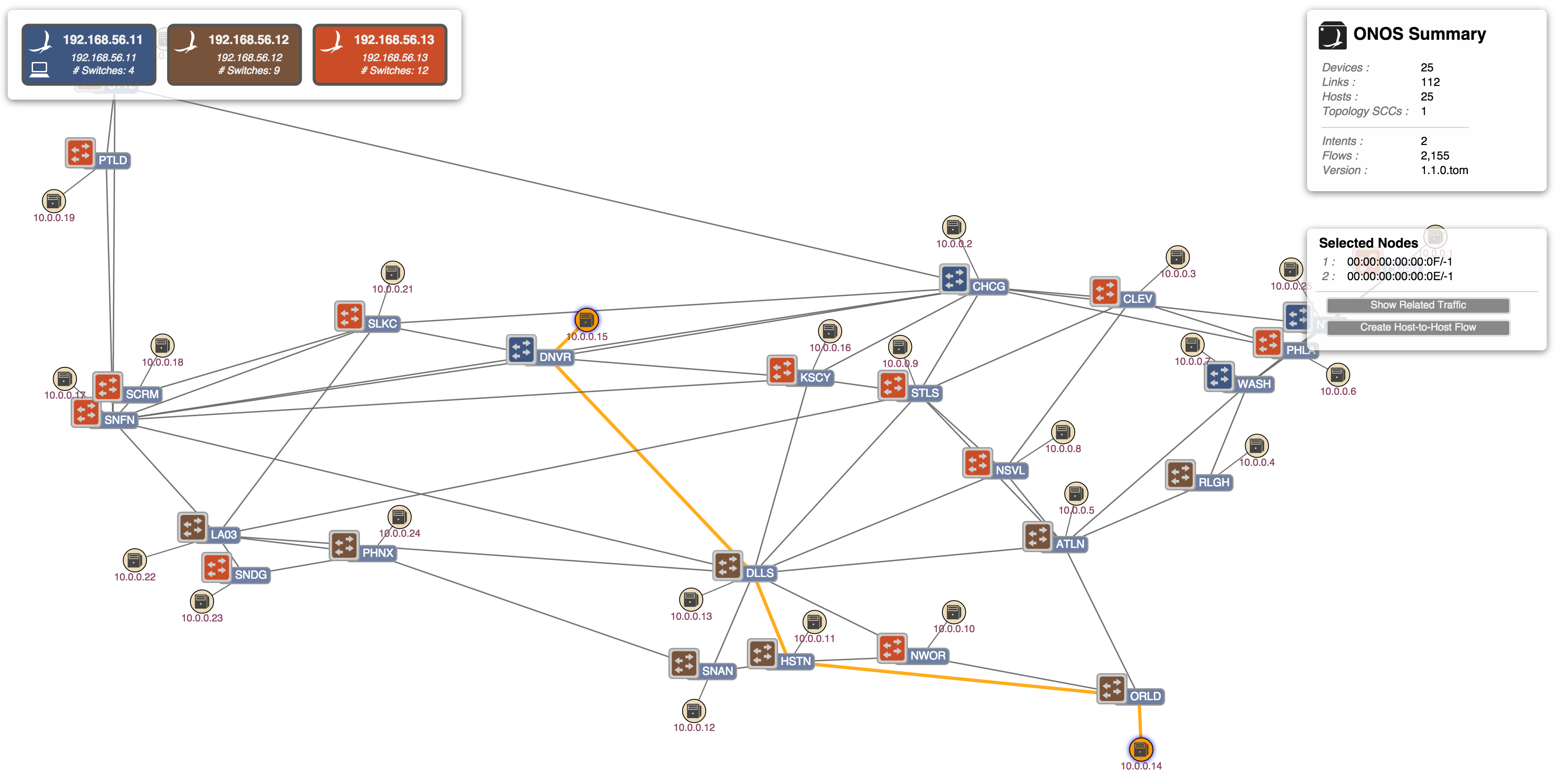
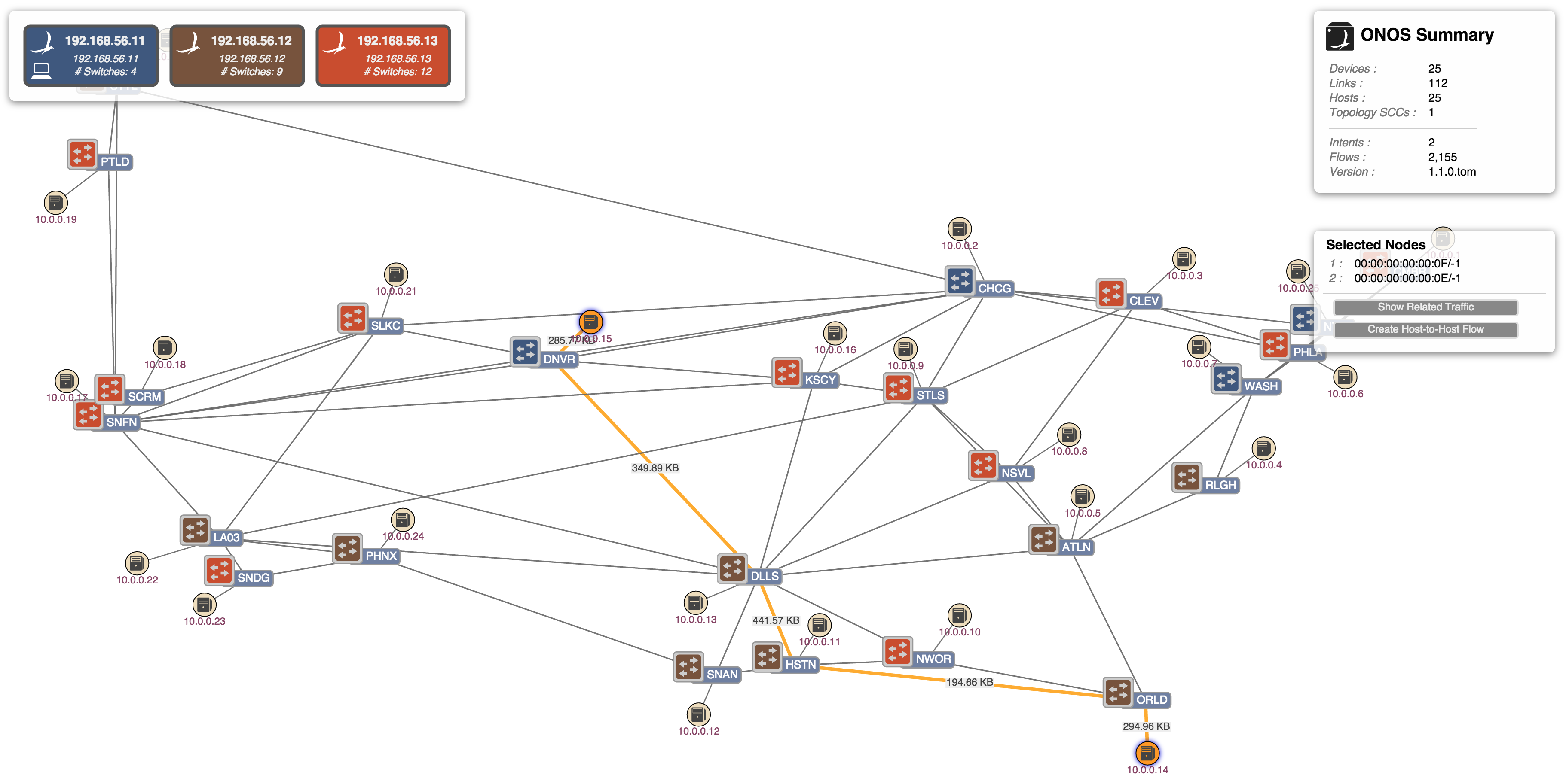
(4) Monitor traffic of selected intent ('W' key pressed). Note the traffic showing as labels on the links:
Show Related Intents
If a device is selected, pressing the 'V' key will show all related intents, i.e. all intents for which the selected device is a part. Note that if multiple devices are selected, a logical AND operation is applied, meaning that only those intents for which all the selected devices are a part will be highlighted.
...
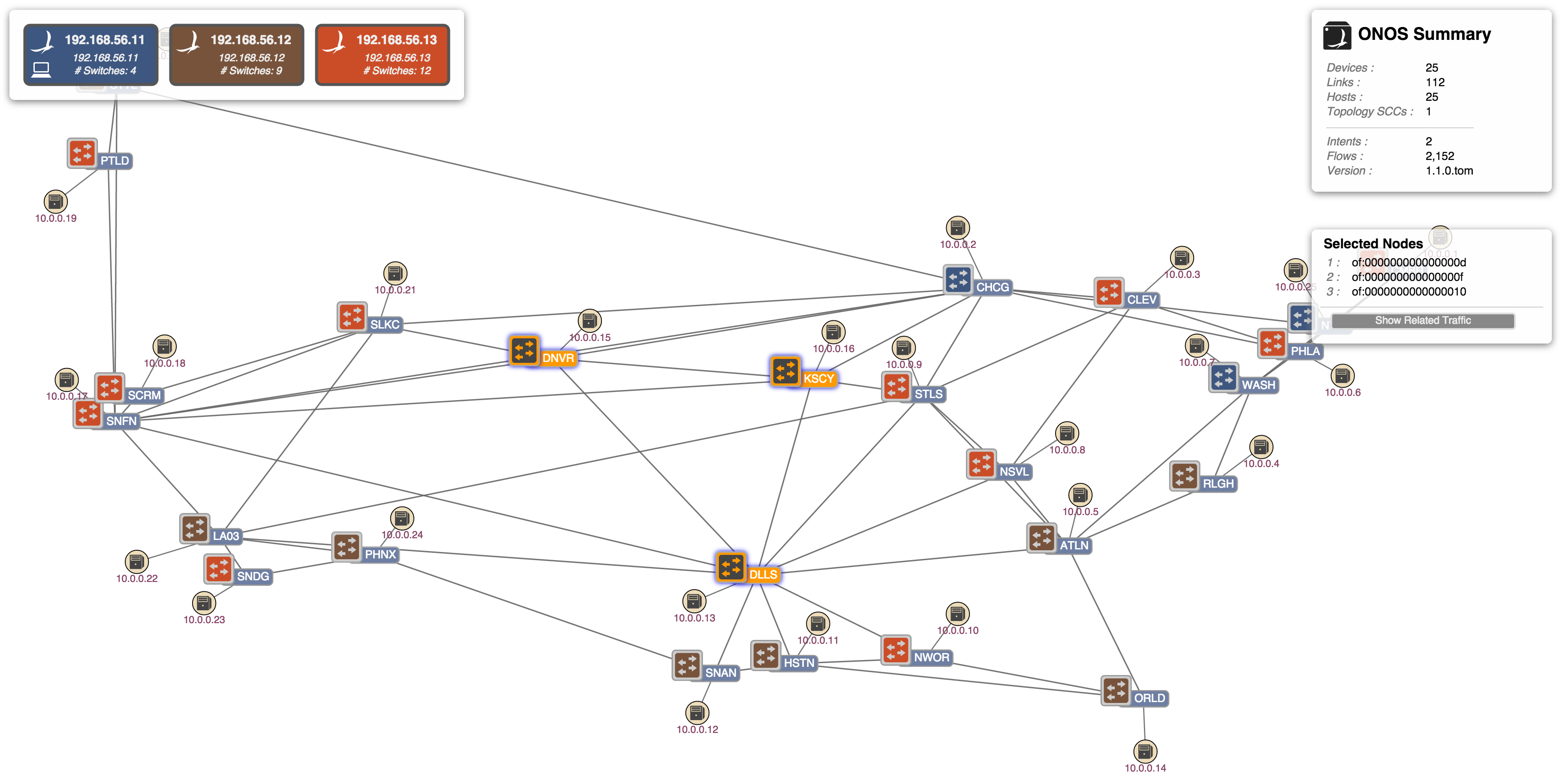
(2) There are no related intents that pass through Denver (DNVR), Dallas (DLLS), and Kansas City (KSCY):
A Set of Related Intents
It is quite probable that a device will be associated with a set of intents. For our example here, let's set up two more host-to-host intents that pass through Dallas:
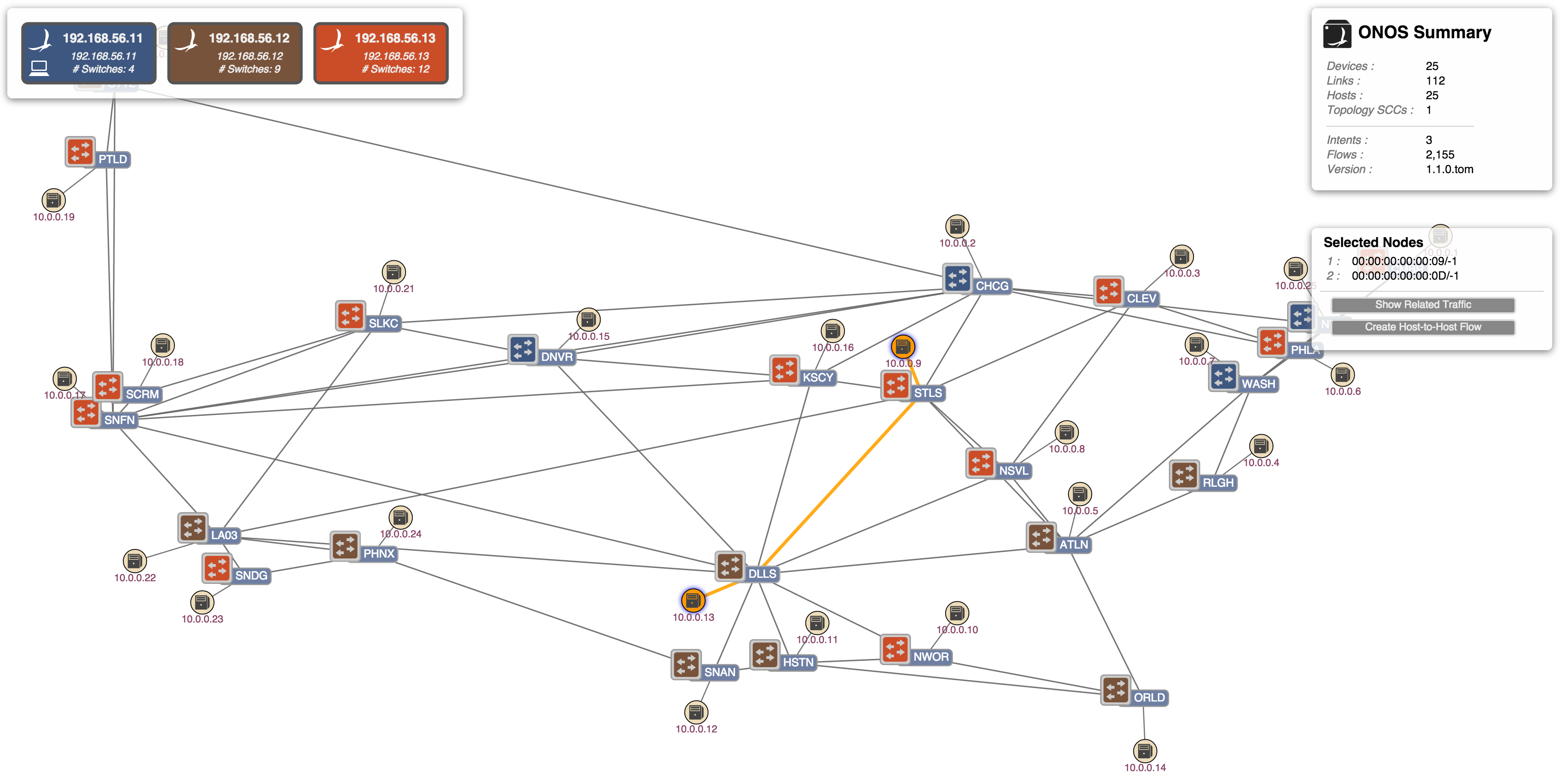
(1) From host (.13) at Dallas (DLLS) to host (.9) at St Louis (STLS):
Related intents (TODO)
...
(2) From host (.12) at San Antonio (SNAN) to host (.2) at Chicago (CHCG):
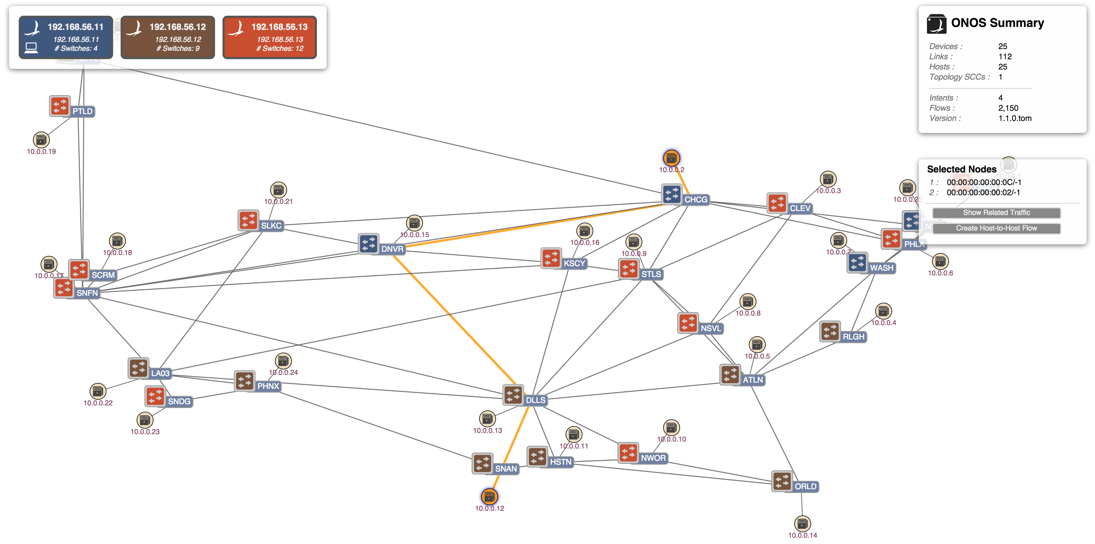
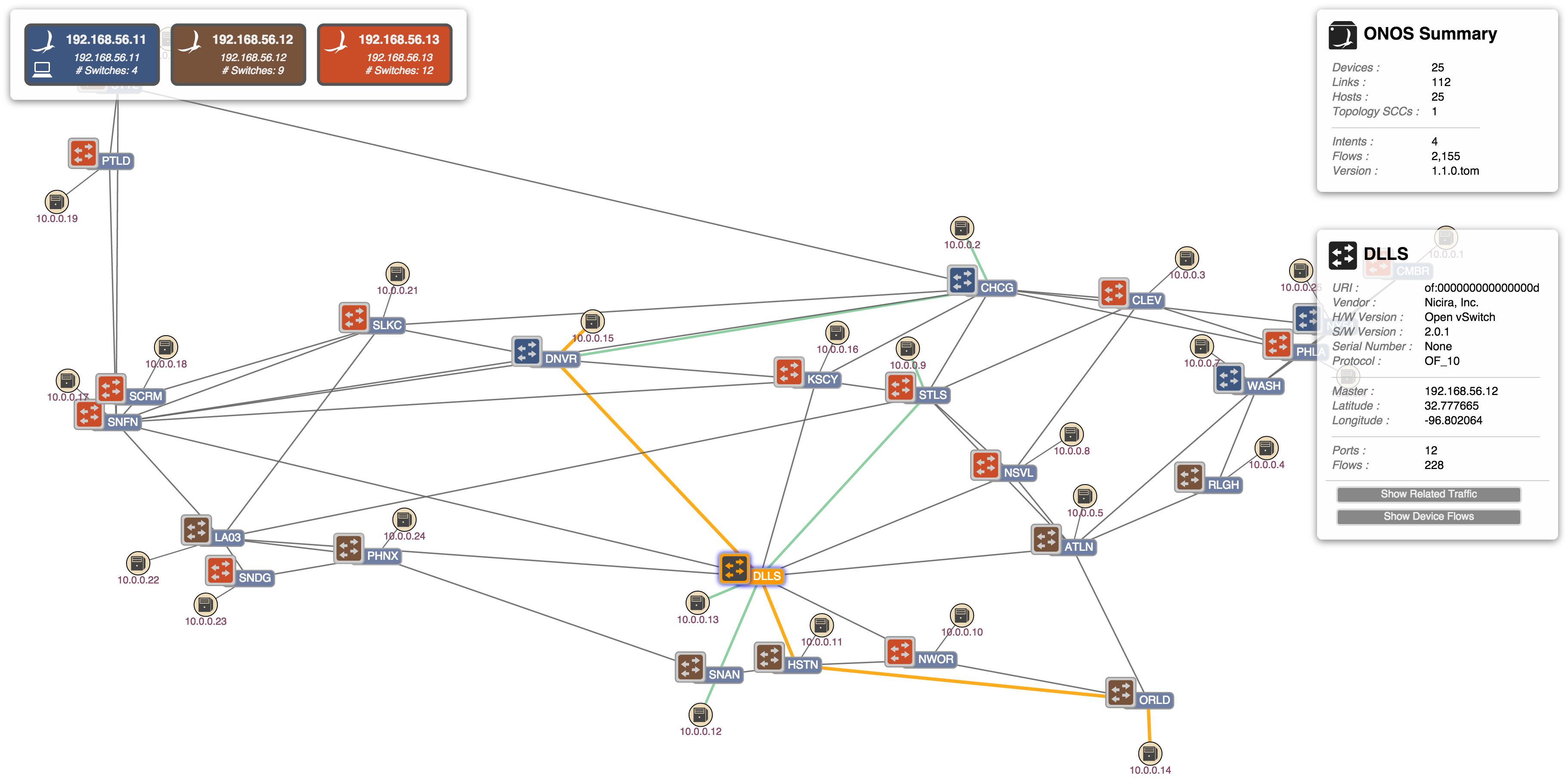
Clearing the selection, then selecting the Dallas device and pressing the 'V' key, we can see the related intents:
Now, by repeatedly pressing the Right-Arrow key (for next-related-intent) or Left-Arrow key (for previous-related-intent), we can step through the intents one at a time. Notice how one intent will be highlighted in orange (the primary selection) and all the other (related) intents are highlighted in green (the secondary selection):
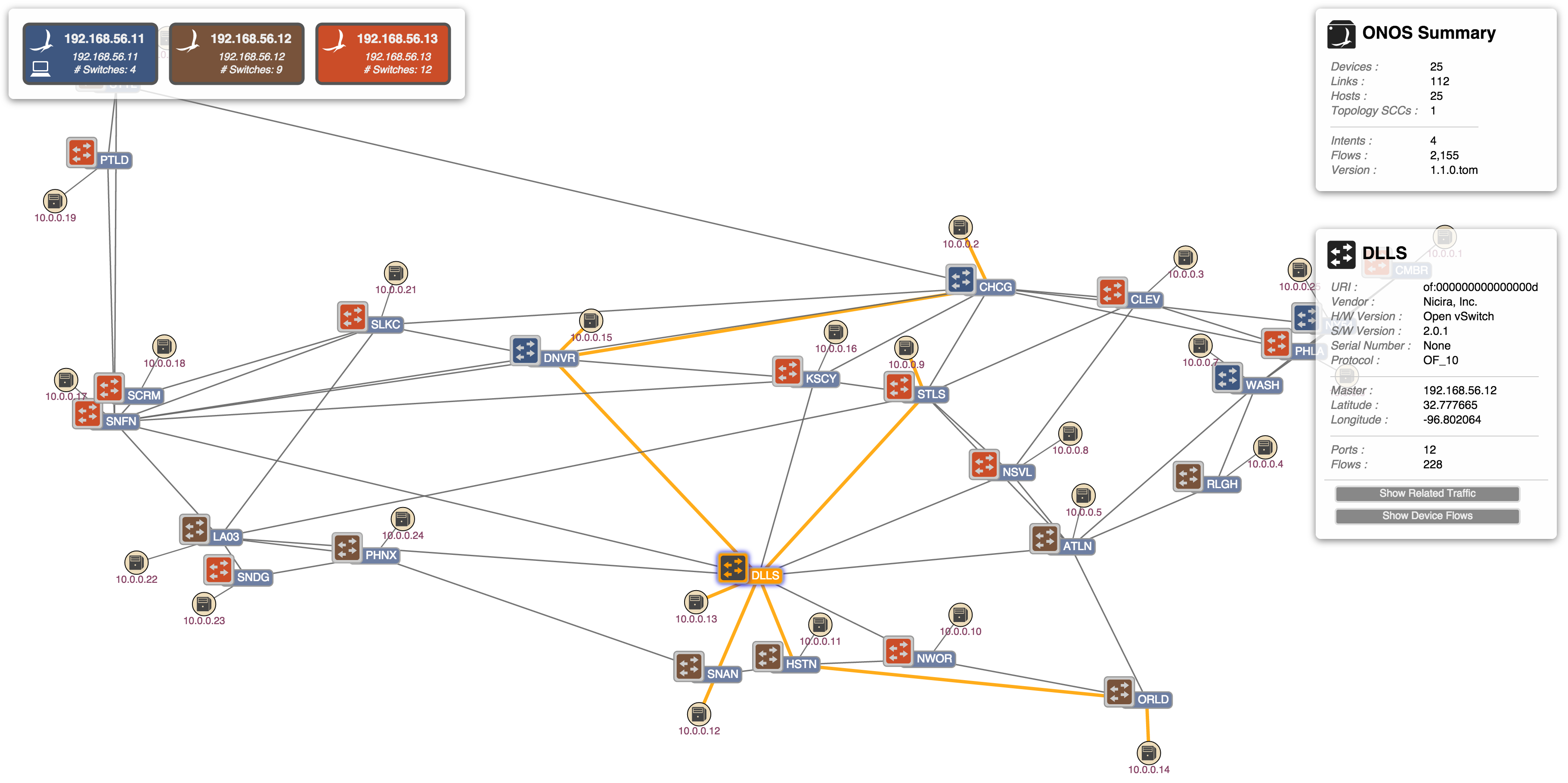
(1) Press '→' key
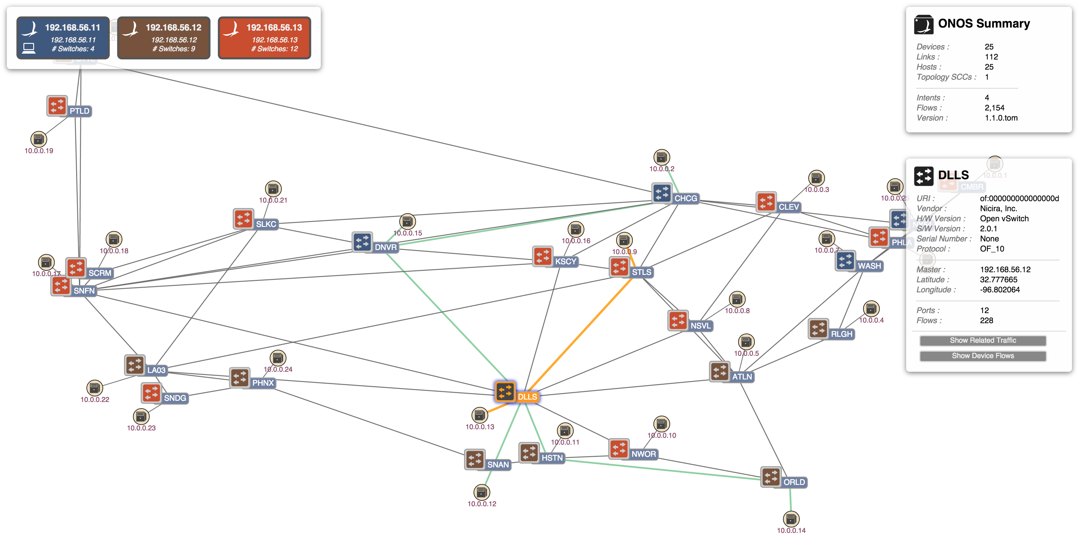
(2) Press '→' key
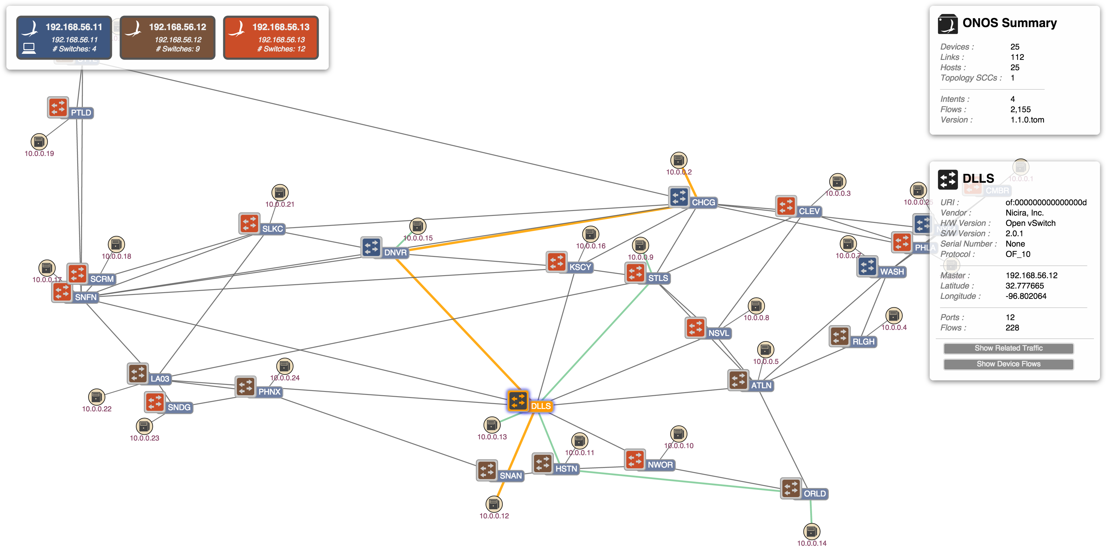
(3) Press '→' key
ONOS Instance Failover
The GUI is designed to detect when the Cluster Instance to which it is connected fails, and to seamlessly "failover" to an alternate cluster member.
(1) Note the three instances, each master of a number of switches (8, 8, and 9, respectively). Note also that the UI is attached to the first instance, as indicated by the icon:
(2) Here, the first instance has failed and the UI has switched over to the second instance. Note also that the remaining two instances have picked up mastership of the switches (now, 9, and 16 respectively):
(3) When the first instance recovers it comes back online, but note how the UI remains attached to the second instance, and also that there is no automatic re-balancing of switch mastership. (now, 0, 9, and 16, respectively):
(4) Pressing the 'E' key sends a command to the server to "Equalize" the mastership roles across the cluster. Note now how the switches have been rebalanced, (now 8, 9, and 8, respectively):
...
Quick Help
By this point you have probably realized that there are a number of "keystroke commands" that can be applied to the topology view. These commands are summarized in a Quick Help panel which can be displayed by pressing the slash '/' or backslash '\' key. Pressing either of these keys again (or pressing the Escape key) will dismiss the panel.
...
The available commands listed in this panel are described in other sections of this page.
Miscellaneous Controls
(TODO)The remaining keystrokes are:
- M - Toggle offline device visibilityE - Equalize mastership roles
- Normally, offline devices are shown as grayed-out icons. This can be toggled to where offline devices are hidden instead.
- B - Toggle background image
- The map of the Continental US can be toggled off and on.
- X - Lock / unlock node positions
- The default is to allow click-and-drag to move nodes (devices & hosts) on the display.
- Z - Toggle oblique view (Experimental)
- This mode will show a "sideways" view of the network, separating packet-layer nodes from optical-layer nodes.
- As noted, this mode is currently experimental.