Due to a ransomware attack, the wiki was reverted to a July 2022 version. . We apologize for the lack of a more recent valid backup.
![]() Under Construction
Under Construction
Welcome to the Packet-Optical ONOS tutorial!!!
In this tutorial, you’ll complete a set of exercises designed to explain the main concepts of the Packet-Optical use case of ONOS. We hope that with this tutorial, you’ll be able to create, configure and start multi-layer networks on your environment, which can potentially represent a wide area network environment for your application performance studies.
To get you started quickly, the converged packet-optical VM is preconfigured with the needed software environments including ONOS, linc-OE, Mininet, Jave-8, Erlang, linc-oe config generator, etc.
You should be able to Just run this VM in VirtualBox using the instructions in the next section.
Introduction
Service Provider Networks are complex and multi-layer in nature. Without converged packet Optical SDN capability, provisioning and adding bandwidth requires order of days, if not months. Since packet and optical networks are managed independently, each one of them has to be over provisioned to deal with traffic anomalies and failures. This leads to lack of service agility and is a significant source of CAPEX and OPEX overhead for the network operator.
This Tutorial demonstrates how ONOS can help address the challenges of managing multilayer service provider networks, by providing a sample demo on how converged packet-optical networks can be controlled by ONOS. We will introduce an emulated environment for converged control of packet and optical networks for wide area network, and show how it will truly enable service providers to use much more efficient traffic management practices.
Additionally, we will show ONOS’s capabilities as an enabler for cross-layer optimization, and applications on the northbound to control the forwarding planes at both the packet and optical layers. This environment can be used by the architects and developers to demonstrate feasibility of applications such as a multilayer PCE (which it’s basics for demonstrating benefits of converged networks.) This part is not very clear.
With Converged Control Plane, we hope to reduce cycle time to add capacity perhaps in minutes instead of days to a month. ONOS has the ability to add capacity based on traffic demand in real- or near real-time. In addition, when failure happens, instead of using the packet layer resources for recovery, ONOS can reconfigure the optical transport layer for best alternative re-route. With this approach, we are reducing the over-provisioning of resources, since transport layer is cheapest infrastructure to move bits. Finally, with enhanced converged control plane, we could potentially enable new services. Examples include network graph observability and real-time injection of network policies.
Prerequisite
You will need a computer with at least 8GB of RAM such that you can dedicate 4 Gig to your packet-optical VM and at least 5GB of free hard disk space. A faster processor or solid-state drive will speed up the virtual machine boot time, and a larger screen will help to manage multiple terminal windows.
The computer can run Windows, Mac OS X, or Linux – all work fine with VirtualBox, the only software requirement.
To install VirtualBox, you will need administrative access to the machine.
The tutorial instructions requires some prior knowledge of SDN in general, and OpenFlow and Mininet in particular. So please first complete the OpenFlow tutorial and the Mininet walkthrough.
Before you try Packet-Optical use case, we highly recommend to complete ONOS tutorial too.
OOPs? Found a bug? Questions?
Email us (onos-discuss@onosproject.org) if you’re stuck, think you’ve found a bug, or just want to send some feedback.
Please have a look at the guidelines to learn how to efficiently submit a bug report.
Setup Your Environment
Install required software
You will need to acquire two files: a VirtualBox installer and the Tutorial VM (Link TBD by Marc) .
After you have downloaded VirtualBox, install it, then go to the next section to verify that the VM is working on your system.
Import pre-configured Virtual Machine
Start up VirtualBox, then select Machine>New, give it a name, and select Linux as type and Ubuntu (64 bit) as version. Press Continue.
Next, configure the VM with 2 GB (2048 MB) of memory. ( If you are going to run the bigger topology, Configure the VM with 4 GM ( 4096) of memory, Press Continue.
Select ‘Use an existing virtual hard drive file’, and point it to the vmdk file you downloaded Select "Create". Note you can also import ".OVA" instead.
Now you can start the VM by double clicking it; once it starts you can login with user "sdn" and password "rocks".
After some time you should see the desktop view for Ubuntu. You can open a terminal by double clicking Terminal.
This VM Contains the following subsystems / files :
1- ONOS; Alternatively "ONOS from Scratch"
2-Mininet; Alternatively "Mininet"
3-Linc-OE, "Linc-OE GitHub"
4- Linc-OE config Generator ; "Config" which generates Sys.config representing Optical Layer Topology
5- Mininet Python Scripts ; which starts mininet, and linc-oe" OpticalTest.py", "opticalTestBig.py"
6- Erlang ;
wget https://packages.erlang-solutions.com/erlang-solutions_1.0_all.deb
sudo dpkg -i erlang-solutions_1.0_all.deb
rm erlang-solutions_1.0_all.deb
sudo apt-get update
sudo apt-get install erlang rebar"How to download Erlang"
7-Java-8; Which could also be downloaded directly from "ONOS from Scratch"
Important Command Prompt
Terminal
$
Symbol "$" means linux terminal.
Mininet
mininet>
"mininet>" means mininet CLI command prompt
Linc-OE
(linc@mininet-vm)1>
"(linc@mininet-vm)1>" means Linc-OE CLI command prompt.
Packet-Optical Topology Spin-Off (via Python-Script)
Go to mininet/examples
You should have a file that contain the packet-optical topology sample " opticalTest.py ". This file is a python script which creates the following topology:
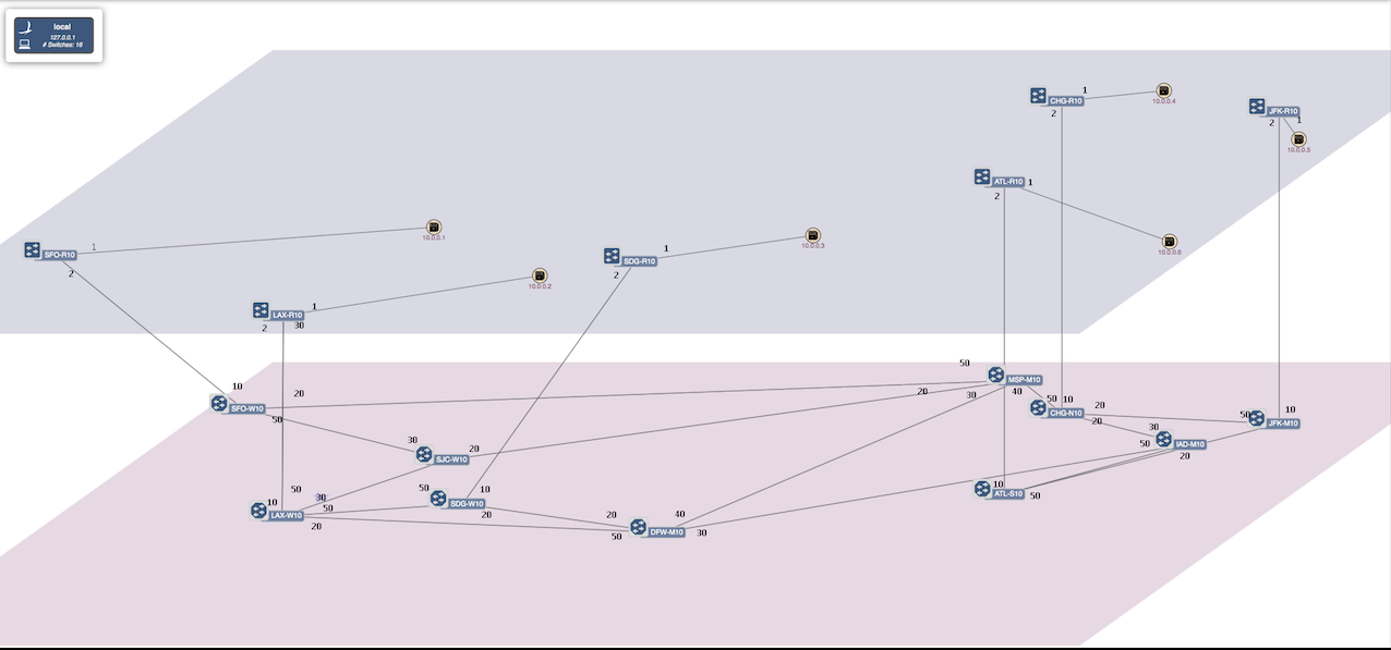
As shown the topology contains 6 packet nodes in upper packet plane, and 10 optical nodes in the lower optical plane.
Each packet node is attached to a host representing a data center. The traffic is typically initiated from Hosts attached to the packet networks.
Note that there is no physical links between the packet nodes. All traffic sourced at the data centers are routed through the optical plane.
The optical plane represents the physical network infrastructure interconnected via ROADMs, and packet network are interconnected via logical links only when a circuit is established through
physical layer.
The tap interfaces are used to interconnect the optical switches and packet nodes. We are utilizing linux tap interfaces for interconnecting the optical switches and packet switches.
Start Mininet and Linc-oe
To start Linc-oe and Mininet go to:
This will create the topology shown above in the figure and ask you to 'Press any key to push Topology.json to onos...'
Before you press any key you need to run ONOS. To run ONOS
or
This will start ONOS. Now you can Press any key to push Topology.json to ONOS.
Demo 1: Establishing connection between hosts/DataCenters using ONOS-GUI.
To get the ONOS-GUI type the following at the terminal:
or
This will open the ONOS-GUI in a tab in you default browser. You can press z to get the split view of packet and optical plane and press h to see hosts (for more options press /). note: using convention of bold font for user keystrokes
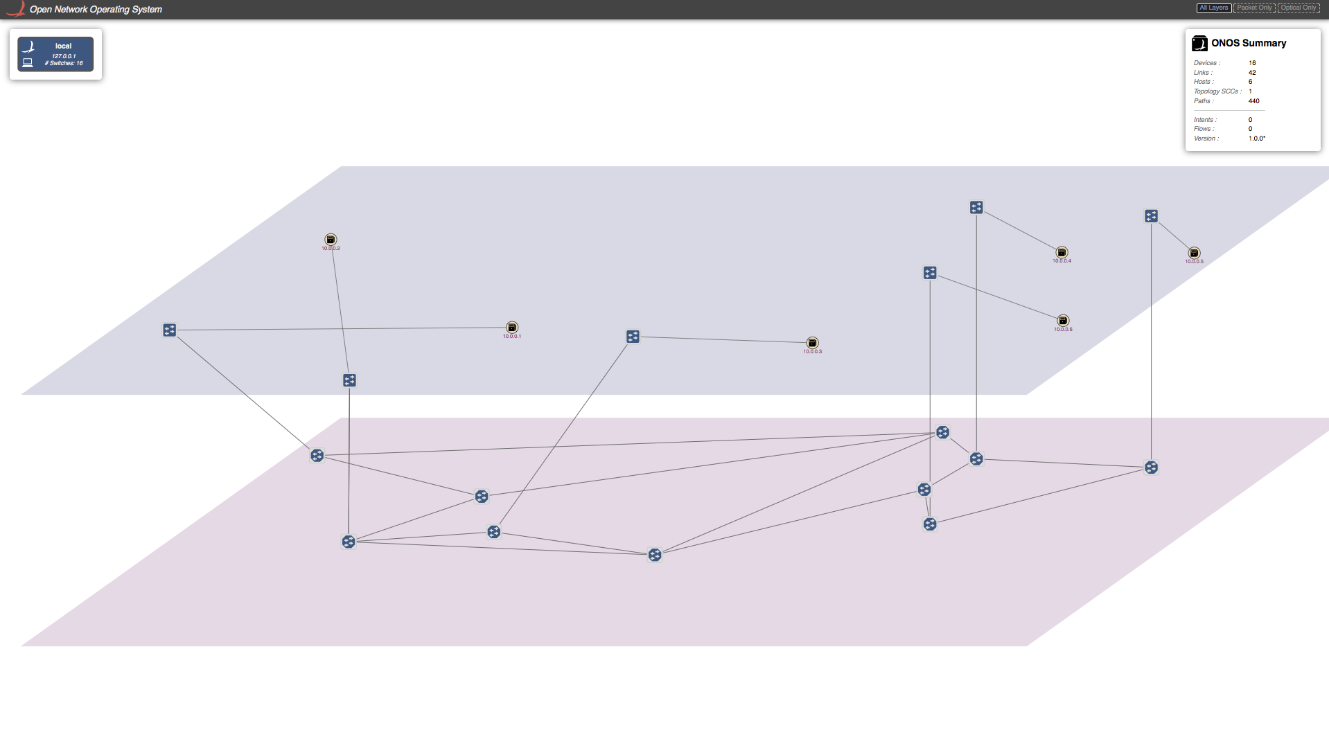
As you can see that there are no host discovered by ONOS. This is due to the fact that ONOS only discovers a host when there is traffic from the host. So let's generate traffic from all hosts.
In the Mininet command prompt:
or you can manually do ping between all the hosts.
Now you should see all the host in ONOS-GUI. It should look something similar to figure below.
Note, no ping will succeed as there is not physical link between packet switches. Let's establish a connection between two packet switches that consist of optical layer. To do so, we need to send a Host-to-Host Intent to ONOS. There are two ways to do this. One is through ONOS-GUI, and other is directly from ONOS-CLI, which we will show in next section.
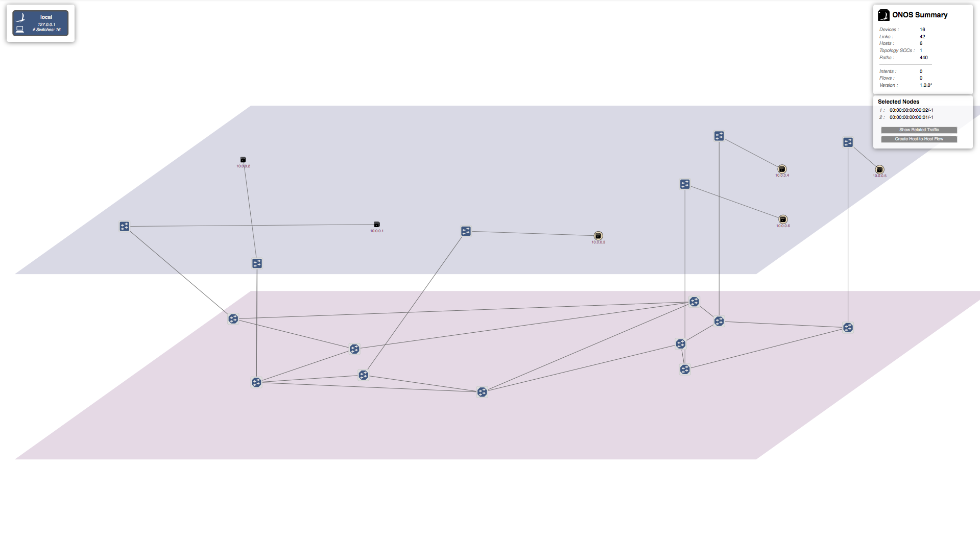
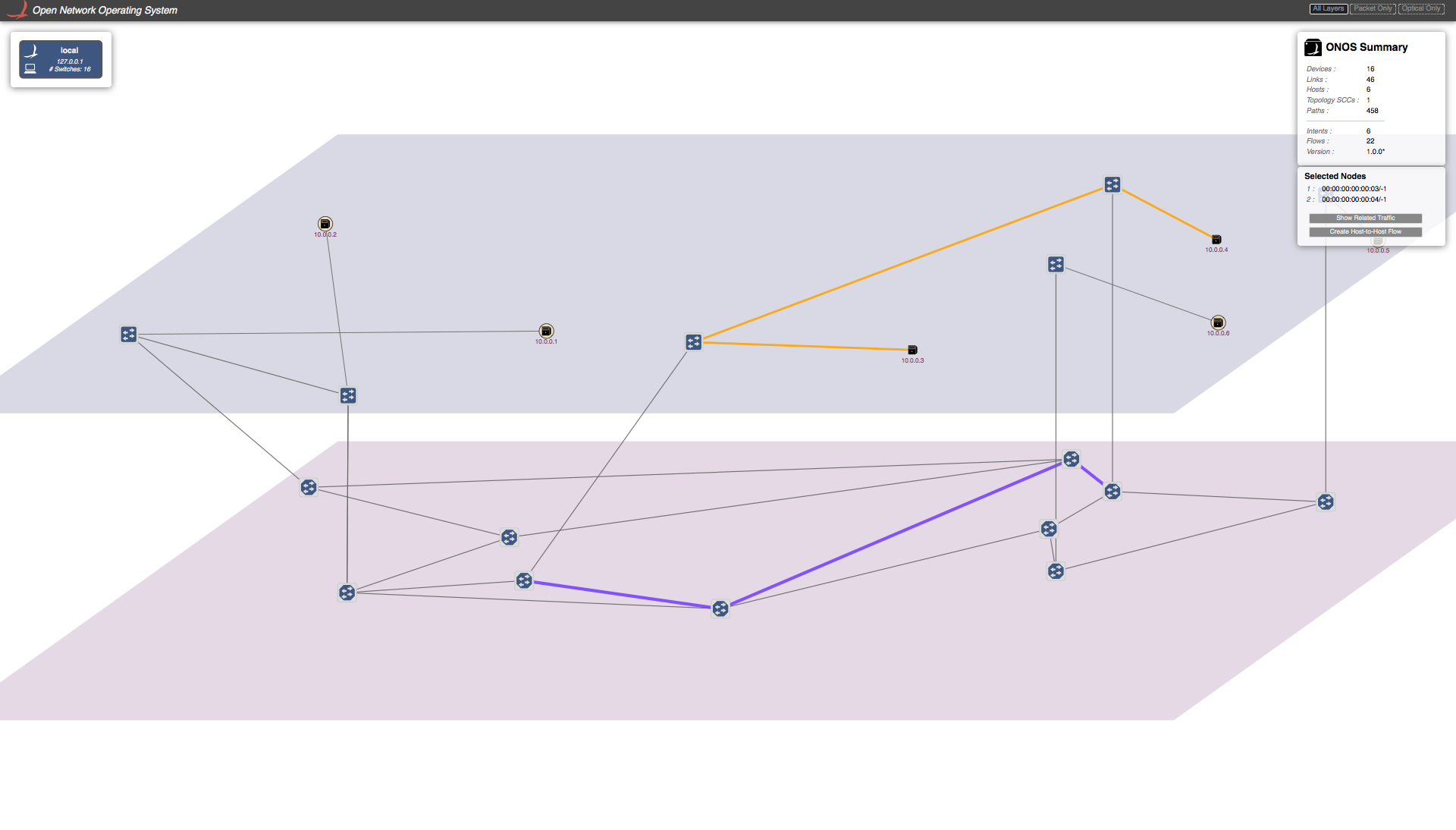
Let's send a Host-to-Host Intent to ONOS using the GUI. To do so, click on the first host and then press left-shift and click on the second host while keep holding the left-shift key. Small window will appear on the right top corner under "ONOS-Summary" window stating "Selected Nodes" as show in figure. For example purpose I have selected hosts with IP=10.0.0.1 (h1) and IP=10.0.0.2 (h2).
Click on "Host-to-Host flow" in "Selected Nodes" window. This sends the Host-to-Host intent to ONOS. ONOS will discover that there is no direct link between two corresponding packet switches but they are reachable through the optical-layer, and hence setup a path through the optical layer. A virtual direct link will created between these packet switches in the GUI as shown in the figure below.
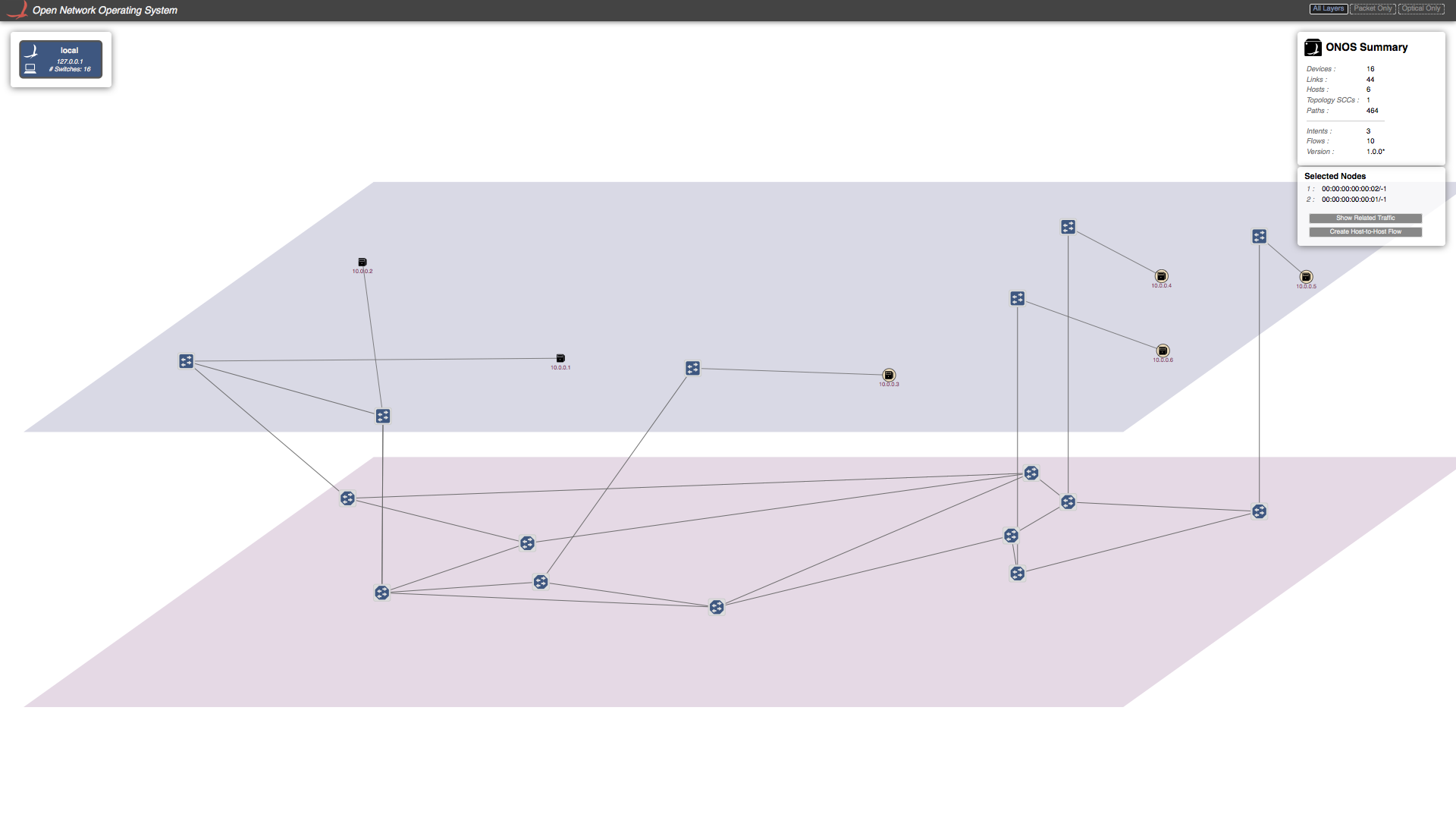
Now if you send traffic between these host you will see traffic is going through successfully. Note in this tutorial script we have only create one tap interface per packet-optical switch. Which means we cannot setup more then one connection per switch. If you want more then one connection per switch you need to add tap interface accordingly in "opticalTest.py".
Demo 2: Establishing connection between hosts/DataCenters using ONOS-CLI.
You can send Host-to-Host intent using ONOS-CLI too. To do so you have to write following command in ONOS-CLI command prompt. For example purpose I have chosen h3 and h4
You will again see the direct virtual link been setup between the switches corresponding to h3 and h4.
There is an other way to send Host-to-Host Intent to ONOS with specified bandwidth using BandwidthCalendaring app which is explained in next section.
Demo 3: Establishing connection between hosts/DataCenters using Calendering app.
TBD
Demo 4: Link recovery from optical layer failures
In this section we gonna demonstrate how failure in optical layer can be recovered by ONOS in pinch on second without disturbing the traffic flow.
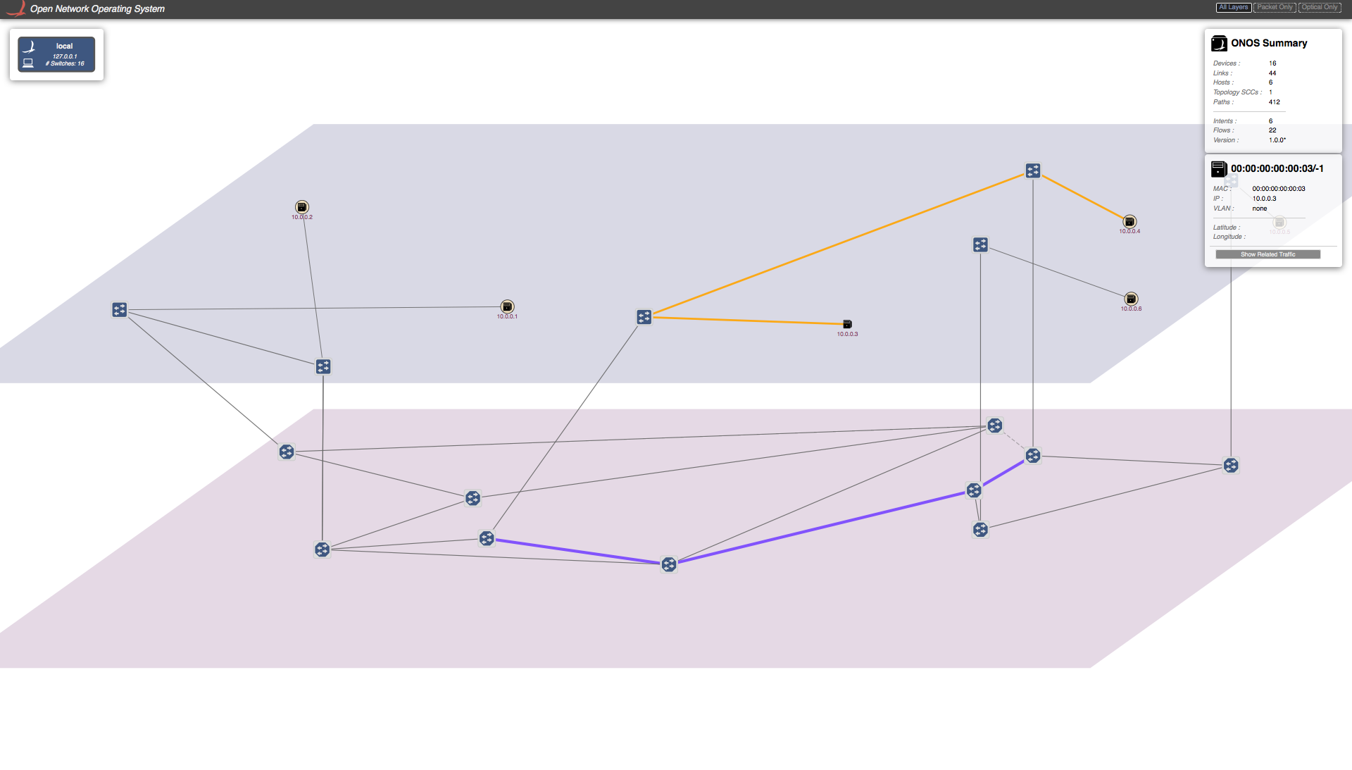
Two see the what path is taken by certain host to send traffic (in GUI of course), you can click on that Host and click on show related traffic. You will see something similar to figure show below.
Yellow path shows packet layer path and purple path shows optical layer path.
Now we will introduce failure in optical path of the traffic flow. We need to get into linc-oe console to introduce failure in optical switch. To do so do following,
This will get you into the command prompt of linc-oe. Now you need to figure out which optical switch's switch port will cause failure in optical path. You do this clicking on any switch in purple path and note the DPID of this switch and the switch connected to this switch (which also must be part of optical path). Now you have to figure out what port on each of these switches is responsible for connecting them together. These many ways but most reliable ways is to look into sys.config. In the separate terminal write following commands
In the logical_switches section look for dpids that you just have noted and note the switch Id corresponds both DIPDS, you will see something like,
In my case switch Id that correspond to DPID "00:00:ff:ff:ff:ff:ff:05" is "7" and DPID ,"00:00:ff:ff:ff:ff:ff:07" correspond to switch Id "2". Note switch Id of both the switches. Now in the same file there is section for optical_links,
In the above list show all the optical links. {{7,40},{2,50}}, means switch_Id 7 port 40 is connected to switch_Id 2 port 50. You need find the link port then you want to bring down. In my case its switch 7 port 40.
We know its hectic a task and we are in the progress of making it easier.
Once you know the switch and port you need to run following command in Linc-oe console to bring that port down.
It will return "ok".
You will see that ONOS will reroute the the traffic as shown in the figure.
Demo 5: Link recovery from packet layer failures
TBD
Playing with bigger topology.
We have also provide python script with bigger topology, "opticalTestBig.py"
We highly encourage you to run that topology and play with it and give us you feed back.