Due to a ransomware attack, the wiki was reverted to a July 2022 version. . We apologize for the lack of a more recent valid backup.
Overview
The ONOS GUI is a single-page web-application with hash-navigation. The GUI system comprises client-side code (a single HTML page structured as an AngularJS application, javascript libraries and modules, CSS files, etc.) and server-side code (Java classes that "model" the GUI views, and interface with ONOS Server APIs to provide the data for those views). The GUI web page is served up by a web server running on an ONOS instance.
Client-Side Architecture
From the web-browser's point of view, the client side code is comprised of:
| The main application page |
|
| Third party libraries |
|
Framework code |
|
| Supporting framework utilities |
|
Core Views (installed with out-of-the-box ONOS) |
|
... along with their associated *.css stylesheets.
Notes:
For the following notes, the "wiring" can be seen by examining the web.xml configuration file.
(1) index.html is generated dynamically via the MainIndexResource class. The index.html file is used as a template, with javascript <script> elements and style sheet <link> elements injected where indicated. The contents of these sections are composed by querying all UiExtensions registered with the UiExtensionService.
(2) onos.js is generated dynamically via the MainModuleResource class. The onos.js file is used as a template, with view IDs injected where indicated. The list of view IDs is generated by iterating across the UiViews defined by each registered UiExtension.
(3) nav.html is an HTML fragment generated dynamically via the MainNavResource class. The nav.html file is used as a template, with the navigation category headers and links injected where indicated. The headers and links are generated by iterating across the category values, and within each category iterating across the UiViews (for that category) defined by each registered UiExtension.
Injected Views
Additional views can be injected into the GUI at runtime. Each view has a unique identifier (e.g. "myviewid"). The following convention should be used to place client-side resources in the .oar file:
|+-- resources| +-- <UiExtId>| +-- css.html| +-- js.html|+-- webapp +-- app +-- view +-- <viewid1> | +-- *.css | +-- *.html | +-- *.js | +-- <viewid2> +-- *.css +-- *.html +-- *.js
where <UiExtId> is the unique ID of the UiExtension instance, and <viewid1> and <viewid2> are the unique IDs of the views provided by the extension.
Server-Side Architecture
The ONOS GUI has a corresponding server-side presence (on each ONOS instance in the cluster) which is exposed as the UiExtensionService. The following figure illustrates the relationships between the various components:
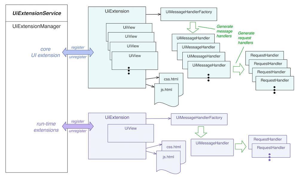
The UiExtensionService provides an API allowing the run-time addition (or removal) of UiExtension instances. The UiExtensionManager implements this service, and automatically registers the "core" UiExtension instance (shown at the top of the figure). ONOS applications may provide their own UiExtension instance, which they will register on activation, and unregister on deactivation (shown at the bottom of the figure).
UiExtension
UiExtension instances provide:
- a unique internal identifier (e.g. "core")
- a UiMessageHandlerFactory which generates UiMessageHandlers on demand, each of which generate RequestHandlers.
- one or more UiViews; these are server side "model" objects each representing a "view" in the GUI.
- two .html snippets providing linkage for injected .css and .js resources.
Note that there is generally a 1:1 correspondence between UiViews and UiMessageHandlers; the message handler providing a request handler for each request type that the view sends from the client to the server.
UiView
UiView instances are immutable objects that encapsulate information about a view:
- A Category; (currently, PLATFORM, NETWORK, OTHER, or HIDDEN)
- An internal identifier (e.g. "topo")
- A label (display string, e.g. "Topology")
- An icon identifier (e.g. "nav_topo")
CSS and JS Linkage
The files css.html and js.html should be provided under the resources directory. These snippets are injected into index.html to provide the necessary linkage to the stylesheets and JavaScript required for the injected views.
|+-- resources +-- <UiExtId> +-- css.html +-- js.html
A sample css.html file might look like this:
<link rel="stylesheet" href="app/view/myviewid/myviewid.css">
A sample js.html file might look like this:
<script src="app/view/myviewid/myviewMain.js"></script>
<script src="app/view/myviewid/myviewUtil.js"></script>
UiMessageHandlerFactory
The UiMessageHandlerFactory is responsible for generating a set of UiMessageHandlers on demand. These are requested when a GUI connection comes into the server, to serve that GUI instance.
Under review from here down.....
Topology Model (to be moved to another page)
The UI maintains an internal model of the topology by storing data representing ONOS instances, nodes (devices and hosts) and links. The model is empty initially, but is augmented as events (such as addInstance, addDevice, addLink, etc.) come in from the server. As these events arrive, the model is updated and the visual representation modified to reflect the current model.
Client-Server Communication
The Topology View uses a websocket to establish communication with the server. This provides a dedicated TCP connection along which the client and the server can emit messages to the other side. The server sends messages to the client describing status updates and/or changes to the topology; the client sends messages to the server, in response to gestures made in the UI by the user, requesting actions to be performed or requesting additional data.
Event messages are structured JSON objects, with the following general format:
{
  "event": "eventType",
  "sid": ... ,
  "payload": {
    ...
  }
}
The event field is a string uniquely identifying the event type.
The sid field is an optional sequence identifier (monotonically increasing integers) which, if provided by the client, should be duplicated in the server's response to that event. Note that, in general, server-initiated events do not include a sid field.
The payload field is an arbitrary JSON object the structure of which is implied by the event type. Many payloads include an id field at the top level, which holds the unique ID of the item being described by the event.
Event Descriptions
The following table enumerates the events, providing a high-level description of the payload. For explicit details of the payloads, see the source-code ![]() .
.
Note that the term "node" (in this context) is used to mean "device or host node" in the topology visualization.
| Source | Event Type | Description of Payload | Trigger | Comments |
|---|---|---|---|---|
| UI | requestSummary | (no payload) | Summary pane shown | Client requesting the server to send topology summary data. |
| Server | showSummary | High level summary properties: total number of devices, links, hosts, ... | Periodic updates in response to requestSummary | The summary data is displayed in a "fly-in" pane in the top right of the view. Note that the server will continue to send these events to keep the summary data up-to-date. |
| UI | cancelSummary | (no payload) | Summary pane hidden | Client requesting the server to stop sending summary data. |
| Server | addInstance | Instance ID, IP address, online status, ... | ONOS instance added to cluster | An ONOS instance to be added to the model. |
| Server | addDevice | Device ID, type, online status, mastership, labels, properties, ... | ONOS discovers new device | A device (switch, roadm, ...) to be added to the model. |
| Server | addHost | Host ID, type, connection point, labels, properties, ... | ONOS discovers new host | A host (endstation, bgpSpeaker, router, ...) to be added to the model. |
| Server | addLink | Link ID, type, source ID/port, destination ID/port, ... | ONOS discovers new link | A link (direct, optical, tunnel, ...) to be added to the model. |
| Server | updateInstance | (same as addInstance) | Instance changes state | An ONOS instance with updated state. |
| Server | updateDevice | (same as addDevice) | Device changes state | A device with updated state. |
| Server | updateHost | (same as addHost) | Host changes state | A host with updated state. |
| Server | updateLink | (same as addLink) | Link changes state | A link with updated state. |
| Server | removeInstance | (same as addInstance)(1) | ONOS instance leaves cluster | An ONOS instance to be removed from the model. |
| Server | removeDevice | (same as addDevice)(1) | Device removed | A device to be removed from the model. |
| Server | removeHost | (same as addHost)(1) | Host removed | A host to be removed from the model. |
| Server | removeLink | (same as addLink)(1) | Link removed | A link to be removed from the model. |
| UI | updateMeta | item ID, item class (device, host, ...) memento data | User drags node to new position | Client requesting data (a memento) associated with a specific node to be stored server-side; That same data (memento) should be returned in the payload of future events pertaining to that node. This mechanism facilitates server-side persistence of client-side meta data, such as the (user-placed) location of a node on the topology map. |
| UI | requestDetails | item ID, item class (device, host, ...) | User selects node on map | Client requesting details for the specified item. |
| Server | showDetails | item ID, item type (switch, roadm, endstation, ...) and list of properties | Response to requestDetails | Server response to requestDetails. |
| UI | addHostIntent‡ | IDs of two selected hosts | 'Create Host-to-Host Flow' action button on multi-select pane. | Client requesting server to install a host-to-host intent. |
| UI | addMultiSourceIntent‡ | IDs of selected nodes (multi source, single destination) | 'Create Multi-Source Flow' action button on multi-select pane. | Client requesting server to install multiple intents. |
| UI | requestRelatedIntents‡ | IDs of selected nodes, ID of hovered-over node | 'V' keystroke | Client requesting intents relating to current selection of nodes be highlighted. |
| UI | requestPrevRelatedIntent‡ | (no payload) | 'L-arrow' keystroke | Client requesting previous related intent to be highlighted |
| UI | requestNextRelatedIntent‡ | (no payload) | 'R-arrow' keystroke | Client requesting next related intent to be highlighted |
| UI | requestSelectedIntentTraffic‡ | (no payload) | 'W' keystroke | Client requesting continuous monitoring of traffic on the links of the selected intent |
| UI | requestDeviceLinkFlows‡ | IDs of selected nodes, ID of hovered-over node | 'F' keystroke | Client requesting continuous monitoring of flow rules on the egress links of the selected device(s) |
| UI | requestAllTraffic‡ | (no payload) | 'A' keystroke | Client requesting continuous monitoring of traffic on all network infrastructure links |
| Server | showTraffic | list of paths (sets of link IDs) and labels to apply to those links, as well as the styling classes to apply to those paths | Response to UI requests marked with ‡ | Server response to requestTraffic. Note that the server will continue to send these events to keep updating the display. |
| UI | cancelTraffic | (no payload) | 'ESC' keystroke | User cancels selection – Client requesting the server to stop sending traffic updates. |
| UI | equalizeMasters | (no payload) | 'E' keystroke | Client requesting server to rebalance mastership of devices across the cluster. |
Notes:
(1) Technically, only the ID field is required, but the server-side code is simplified by using the payload as is.
A Note about Links
The topology model on the server side represents links as unidirectional, with a source and destination. In the UI, each link model object abstracts away the directionality. This is to provide a single "link" element between two "nodes" in the visualization. However, this makes the link event processing a little more complex. Internally the links are modeled something like this:
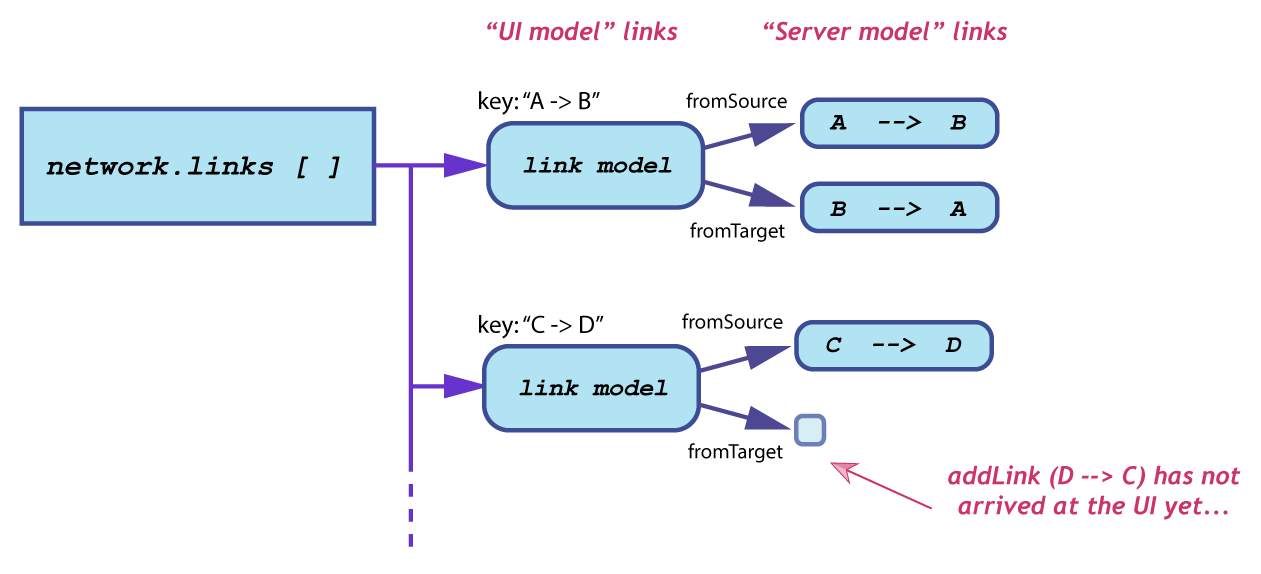
When a link event arrives, a lookup is done to see if the "parent" object for that link already exists.
Server-Side Architecture
Websocket Servlet
When the topology view is loaded it makes an HTTP request to ws://<server>/onos/ui/ws/topology URL. This requests gets upgraded into a Web-Socket, thus establishing a symmetric and persistent connection between the client and the server. On the server side, this process is facilitated by GuiWebSocketServlet, which extends Jetty WebSocketServlet and results in creation of a session-specific TopologyViewWebSocket instance. This instance holds the necessary session-state for interacting with this specific client.
Topology Resources
The following Java classes comprise the server-side code for the Topology View:
TopologyResource- provides REST API for some auxiliary functionality, e.g. export of GEO location dataTopologyViewIntentFilter- responsible for identifying list of intents which pertain to the specified sets of end-station hosts or infrastructure devicesTopologyViewMessages- base class for composing various messages destined for the client and parsing those that were received from the clientTopologyViewWebSocket- main controller for processing inbound messages and emitting appropriate responses
To see the server-side handling of the UI, take a look at TopologyViewWebSocket, in particular the web socket methods:
- onOpen()
- onMessage()
- onClose()
Previous : The Intent Framework
Use Cases : Architecture