Due to a ransomware attack, the wiki was reverted to a July 2022 version. . We apologize for the lack of a more recent valid backup.
Overview
NOTE: The GUI architecture is migrating to use the AngularJS framework – some of the information on this page is deprecated (the topo events are still good).
The ONOS GUI is a single-page web-application with hash-navigation. The GUI system comprises client-side code (a single HTML page, javascript libraries and modules, CSS files, etc.) and server-side code (Java classes that interface to ONOS Server APIs). The GUI web page is served up by a web server running on an ONOS instance.
Client-Side Architecture (Deprecated)
The client side code is comprised of:
| The main application page |
|
| Third party libraries |
|
Framework code and supporting modules |
|
| Supporting libraries |
|
| Topology view |
|
| View module templates |
|
| Sample views |
|
... along with their associated *.css stylesheets.
The structure of the framework allows for the registration of multiple "views" and the subsequent navigation between them.
For the first release, however, there is but a single view, the Topology View.
View Registration (Deprecated)
A view registers with the framework via a call to the addView(...) function.
onos.ui.addView('viewId', {
    init: init,
    reset: reset,
    load: load,
    unload: unload,
    resize: resize,
    theme: theme
});
The first argument to the function is a short string identifier for the view.
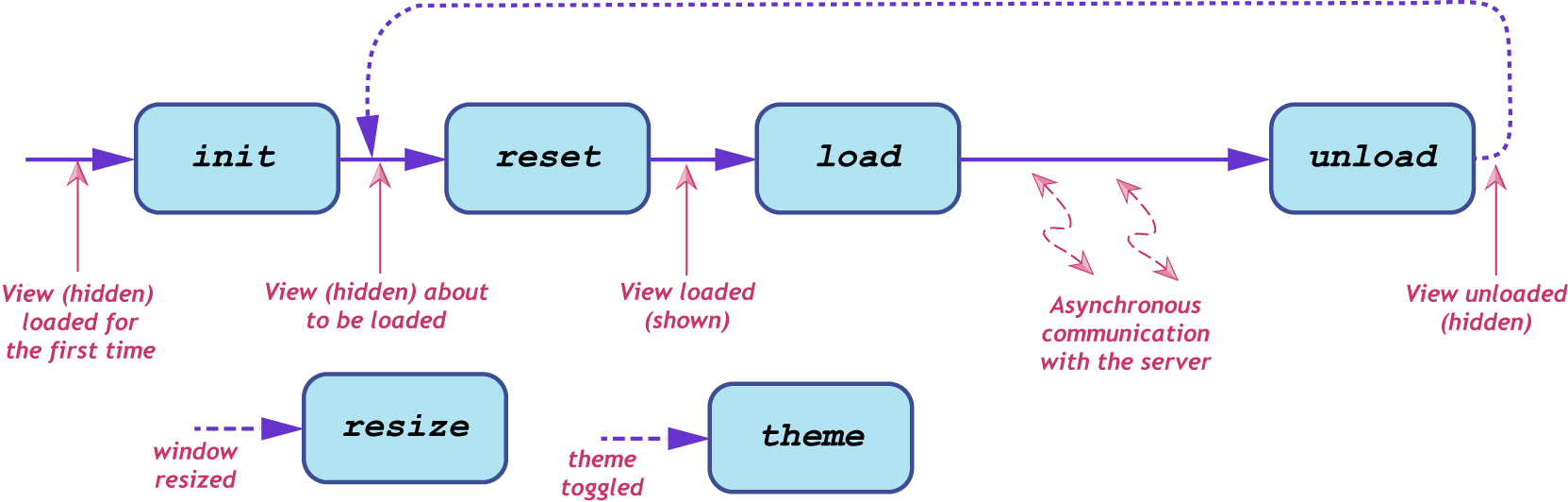
The second argument to the function is an inline object block with the given keys, whose values are references to view life-cycle callback functions:
| init | This function is called only once, the first time the view is loaded. It is called after the view's <div> has been added to the DOM. |
| reset | This function is called just before the view is shown. It can be used to clear stale data from the view. |
| load | This function is called when the view is loaded. |
| unload | This function is called when the view is unloaded. The view may use this to drop references to cached data, or stop background tasks. |
| resize | This function is called when the view has been resized. |
| theme | This function is called when the user has toggled the theme. |
Topology View (Deprecated)
In the first release, the Topology View is the only view available; it is loaded at GUI startup. The following paragraphs summarize each of the view's callbacks:
Init
The init callback is used to initialize the view's SVG layer (including pan and zoom controls) and the Force Layout used to visualize the topology.
Reset
The reset callback is not needed, and thus not implemented.
Load
The load callback starts by injecting the radio button set into the masthead and registering key bindings and mouse gesture descriptions. After that, it performs an asynchronous load of the background GeoMap (Continental USA), before finally opening a websocket connection to the server.
Once the websocket is established, an initial requestSummary event is sent to the server. The UI then processes incoming events from the server to build up a view of the topology. See Event Descriptions below.
Unload
The unload callback cancels the background timer, if it is running.
Resize
The resize callback updates the size of the SVG layer.
Theme
The theme callback updates instance and device colors.
Topology Model
The UI maintains an internal model of the topology by storing data representing ONOS instances, nodes (devices and hosts) and links. The model is empty initially, but is augmented as events (such as addInstance, addDevice, addLink, etc.) come in from the server. As these events arrive, the model is updated and the visual representation modified to reflect the current model.
Client-Server Communication
The Topology View uses a websocket to establish communication with the server. This provides a dedicated TCP connection along which the client and the server can emit messages to the other side. The server sends messages to the client describing status updates and/or changes to the topology; the client sends messages to the server, in response to gestures made in the UI by the user, requesting actions to be performed or requesting additional data.
Event messages are structured JSON objects, with the following general format:
{
  "event": "eventType",
  "sid": ... ,
  "payload": {
    ...
  }
}
The event field is a string uniquely identifying the event type.
The sid field is an optional sequence identifier (monotonically increasing integers) which, if provided by the client, should be duplicated in the server's response to that event. Note that, in general, server-initiated events do not include a sid field.
The payload field is an arbitrary JSON object the structure of which is implied by the event type. Many payloads include an id field at the top level, which holds the unique ID of the item being described by the event.
Event Descriptions
The following table enumerates the events, providing a high-level description of the payload. For explicit details of the payloads, see the source-code ![]() .
.
Note that the term "node" (in this context) is used to mean "device or host node" in the topology visualization.
| Source | Event Type | Description of Payload | Trigger | Comments |
|---|---|---|---|---|
| UI | requestSummary | (no payload) | Summary pane shown | Client requesting the server to send topology summary data. |
| Server | showSummary | High level summary properties: total number of devices, links, hosts, ... | Periodic updates in response to requestSummary | The summary data is displayed in a "fly-in" pane in the top right of the view. Note that the server will continue to send these events to keep the summary data up-to-date. |
| UI | cancelSummary | (no payload) | Summary pane hidden | Client requesting the server to stop sending summary data. |
| Server | addInstance | Instance ID, IP address, online status, ... | ONOS instance added to cluster | An ONOS instance to be added to the model. |
| Server | addDevice | Device ID, type, online status, mastership, labels, properties, ... | ONOS discovers new device | A device (switch, roadm, ...) to be added to the model. |
| Server | addHost | Host ID, type, connection point, labels, properties, ... | ONOS discovers new host | A host (endstation, bgpSpeaker, router, ...) to be added to the model. |
| Server | addLink | Link ID, type, source ID/port, destination ID/port, ... | ONOS discovers new link | A link (direct, optical, tunnel, ...) to be added to the model. |
| Server | updateInstance | (same as addInstance) | Instance changes state | An ONOS instance with updated state. |
| Server | updateDevice | (same as addDevice) | Device changes state | A device with updated state. |
| Server | updateHost | (same as addHost) | Host changes state | A host with updated state. |
| Server | updateLink | (same as addLink) | Link changes state | A link with updated state. |
| Server | removeInstance | (same as addInstance)(1) | ONOS instance leaves cluster | An ONOS instance to be removed from the model. |
| Server | removeDevice | (same as addDevice)(1) | Device removed | A device to be removed from the model. |
| Server | removeHost | (same as addHost)(1) | Host removed | A host to be removed from the model. |
| Server | removeLink | (same as addLink)(1) | Link removed | A link to be removed from the model. |
| UI | updateMeta | item ID, item class (device, host, ...) memento data | User drags node to new position | Client requesting data (a memento) associated with a specific node to be stored server-side; That same data (memento) should be returned in the payload of future events pertaining to that node. This mechanism facilitates server-side persistence of client-side meta data, such as the (user-placed) location of a node on the topology map. |
| UI | requestDetails | item ID, item class (device, host, ...) | User selects node on map | Client requesting details for the specified item. |
| Server | showDetails | item ID, item type (switch, roadm, endstation, ...) and list of properties | Response to requestDetails | Server response to requestDetails. |
| UI | addHostIntent‡ | IDs of two selected hosts | 'Create Host-to-Host Flow' action button on multi-select pane. | Client requesting server to install a host-to-host intent. |
| UI | addMultiSourceIntent‡ | IDs of selected nodes (multi source, single destination) | 'Create Multi-Source Flow' action button on multi-select pane. | Client requesting server to install multiple intents. |
| UI | requestRelatedIntents‡ | IDs of selected nodes, ID of hovered-over node | 'V' keystroke | Client requesting intents relating to current selection of nodes be highlighted. |
| UI | requestPrevRelatedIntent‡ | (no payload) | 'L-arrow' keystroke | Client requesting previous related intent to be highlighted |
| UI | requestNextRelatedIntent‡ | (no payload) | 'R-arrow' keystroke | Client requesting next related intent to be highlighted |
| UI | requestSelectedIntentTraffic‡ | (no payload) | 'W' keystroke | Client requesting continuous monitoring of traffic on the links of the selected intent |
| UI | requestDeviceLinkFlows‡ | IDs of selected nodes, ID of hovered-over node | 'F' keystroke | Client requesting continuous monitoring of flow rules on the egress links of the selected device(s) |
| UI | requestAllTraffic‡ | (no payload) | 'A' keystroke | Client requesting continuous monitoring of traffic on all network infrastructure links |
| Server | showTraffic | list of paths (sets of link IDs) and labels to apply to those links, as well as the styling classes to apply to those paths | Response to UI requests marked with ‡ | Server response to requestTraffic. Note that the server will continue to send these events to keep updating the display. |
| UI | cancelTraffic | (no payload) | 'ESC' keystroke | User cancels selection – Client requesting the server to stop sending traffic updates. |
| UI | equalizeMasters | (no payload) | 'E' keystroke | Client requesting server to rebalance mastership of devices across the cluster. |
Notes:
(1) Technically, only the ID field is required, but the server-side code is simplified by using the payload as is.
A Note about Links
The topology model on the server side represents links as unidirectional, with a source and destination. In the UI, each link model object abstracts away the directionality. This is to provide a single "link" element between two "nodes" in the visualization. However, this makes the link event processing a little more complex. Internally the links are modeled something like this:
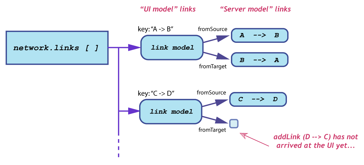
When a link event arrives, a lookup is done to see if the "parent" object for that link already exists.
Server-Side Architecture
Websocket Servlet
When the topology view is loaded it makes an HTTP request to ws://<server>/onos/ui/ws/topology URL. This requests gets upgraded into a Web-Socket, thus establishing a symmetric and persistent connection between the client and the server. On the server side, this process is facilitated by GuiWebSocketServlet, which extends Jetty WebSocketServlet and results in creation of a session-specific TopologyViewWebSocket instance. This instance holds the necessary session-state for interacting with this specific client.
Topology Resources
The following Java classes comprise the server-side code for the Topology View:
TopologyResource- provides REST API for some auxiliary functionality, e.g. export of GEO location dataTopologyViewIntentFilter- responsible for identifying list of intents which pertain to the specified sets of end-station hosts or infrastructure devicesTopologyViewMessages- base class for composing various messages destined for the client and parsing those that were received from the clientTopologyViewWebSocket- main controller for processing inbound messages and emitting appropriate responses
To see the server-side handling of the UI, take a look at TopologyViewWebSocket, in particular the web socket methods:
- onOpen()
- onMessage()
- onClose()
Previous : The Intent Framework
Use Cases : Architecture