Due to a ransomware attack, the wiki was reverted to a July 2022 version. . We apologize for the lack of a more recent valid backup.
Overview
This page describes how to set up a Mininet environment for emulating metro networks. We model a metro network with multiple "central office fabrics" (CPqD soft switches in a clos topology) joined together by a "metro core" of Linc-OE soft ROADMs. The figure below shows the topology that will be emulated - three central offices (blue squares) connected to an optical core of three ROADMs (pink square).
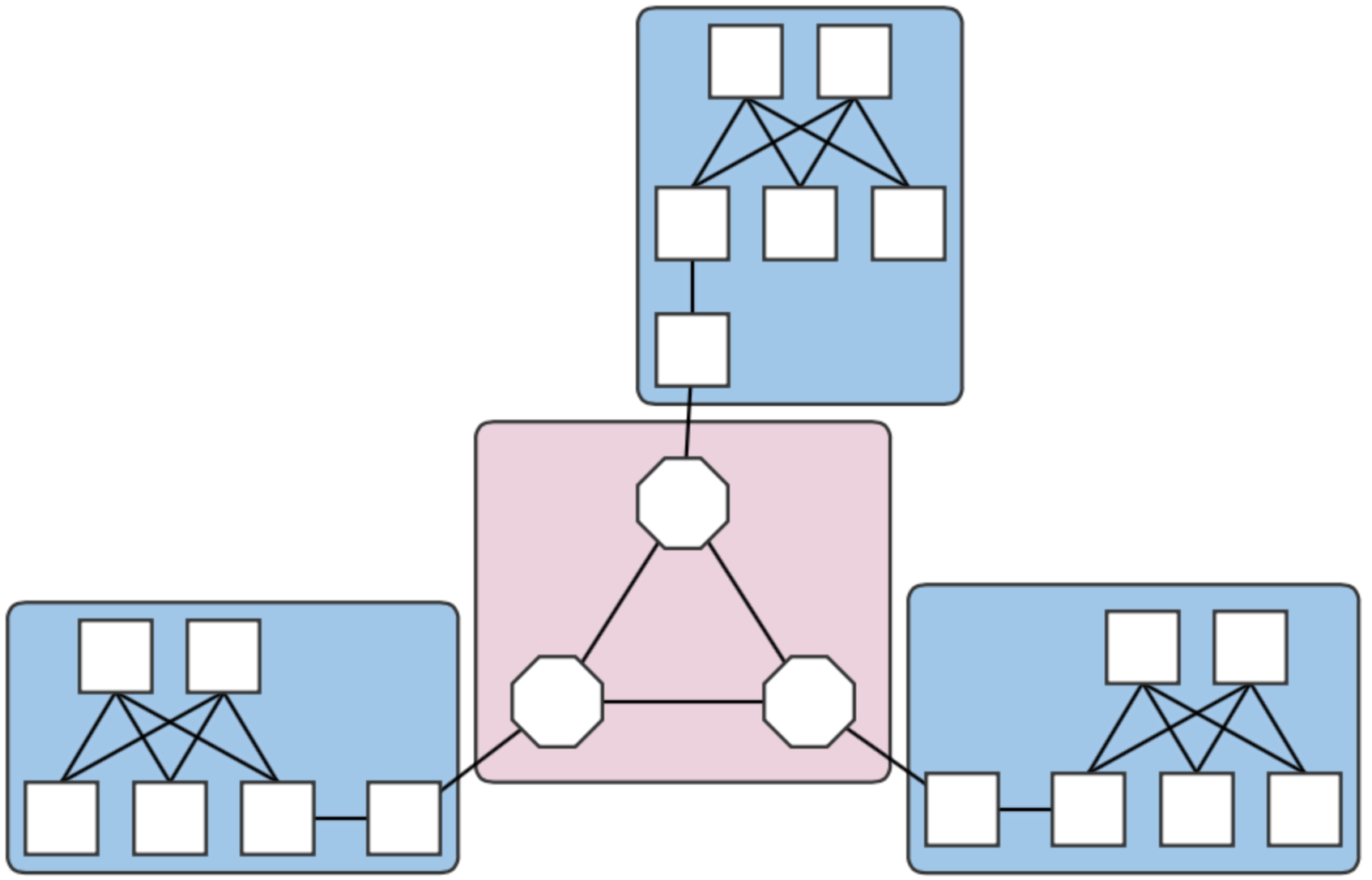
Fig. 1. A four-domain metro network topology.
Each central office and the core are different domains, i.e. regions controlled by different (sets of) controllers. The example above therefore contains four domains. Note that the white squares attaching the clos topologies to the Linc nodes are OVS instances. They are required due to assumptions made in creating links that have Linc-OE endpoints.
Preparation - Mininet VM
The following are the necessary steps to install the required software to emulate a multi-domain network as described above. These instructions assume that the platform is Ubuntu 14.04, x86_64, and a user:password of mininet:mininet has been set up.
Install required packages
sudo apt-get update
sudo apt-get install erlang git-core bridge-utils libpcap0.8 libpcap-dev libcap2-bin uml-utilities curl
Patch and install Mininet. This is required to enable CPqD switches to connect to multiple controllers.
cd
git clone git://github.com/mininet/mininet
cd mininet
wget 'https://wiki.onosproject.org/download/attachments/4164175/multi_controller.patch?version=1&modificationDate=1443649770762&api=v2' -O multi_controller.patch
git apply multi_controller.patch
sudo ./util/install.sh -3fnv
sudo mn --test pingall # this should work
Install Linc-OE
cd
git clone https://github.com/FlowForwarding/LINC-Switch.git linc-oe
cd linc-oe
sed -i s/3000/300000/ rel/files/vm.args
cp rel/files/sys.config.orig rel/files/sys.config
make
cd
git clone https://github.com/FlowForwarding/LINC-config-generator.git
cd LINC-config-generator
cp priv/* .
make
Configure an ONOS development environment. This is required for the Linc-OE portion of the network emulation.
cd
git clone https://github.com/opennetworkinglab/onos
printf '%s\n' '. onos/tools/dev/bash_profile' >> .profile
. .profile
For convenience, set up a cell setting the OC variables to the IPs of the clusters. An instance emulating the network for a four-domain setup might look like the following:
export ONOS_NIC=192.168.64.*
export OC1="192.168.64.45"       # metro core domain
export OC2="192.168.64.46"       # CO 1
export OC3="192.168.64.47"       # CO 2
export OC4="192.168.64.48"       # CO 3
export OCI=$OC1
This allows us to reference OC variables, rather than IP addresses, when we run the emulation script later.
Preparation - Control plane(s)
Environment setup
For ease of deployment, it is best to have a terminal per cell open on the build machine. For simplicity, the deploy targets used for the setup in on this page were separate VMs, and each cluster contained one instance.
Set up cells. Each domain should have a different controller cluster controlling it, and therefore, have separate cell configurations. For example, for two instances at addresses 192.168.64.45 and 192.168.64.46 (the metro core and CO #1), the cell files are:
optical layer - core domain:# cell for core domain (optical network) export ONOS_NIC=192.168.64.* export OC1="192.168.64.45" export OCI=$OC1 export OCN="192.168.64.43" export ONOS_APPS="drivers,openflow,proxyarp,optical"
packet layer - central office 1:
# cell for central office domains (packet networks)
export ONOS_NIC=192.168.64.*
export OC1="192.168.64.46"
export OCI=$OC1
export OCN="192.168.64.43"
export ONOS_APPS="drivers,openflow,proxyarp,segmentrouting"
The remaining COs would have cell files similar to that of CO 1 above, but with
OC1set to their own deploy target host address.Get ONOS and sample application sources and build them. For installation requirements and further detail, refer to Installing and Running ONOS.
git clone https://github.com/opennetworkinglab/onos
cd onos
mvn install -DskipTests -Dcheckstyle.skip
cd ..
git clone https://github.com/opennetworkinglab/onos-app-samples
cd onos-app-samples
mvn install
Prepare component configurations for each CO's virtual big switch application. The file for CO 1 contains the following:
{
    "org.onosproject.ecord.co.BigSwitchDeviceProvider": {
        "providerScheme": "bigswitch1",
        "providerId": "org.onosproject.bigswitch",
        "remoteUri": "grpc://192.168.64.45:11984",
        "metroIp": "192.168.64.45"
    }
}
Note that the value for "providerScheme" should be different for each CO (here, the convention is bigswitchN for CO N). This scheme will be used as part of the virtual switch's device URI/ID. Set the files aside in a known location.
${CFG_LOC}refers to this location in the remainder of this page.
Deployment
This is currently a order-sensitive procedure. The following steps refer to the terminal loaded with the cell, and the CLI for the cluster controlling a domain by its domain. For example, the terminal with the metro cell definitions will be called the 'metro cell', and the CLI of the ONOS instance in that cell, the 'metro CLI'.
Deploy the metro cluster. From the metro cell:
op && onos-install -f
Once booted, activate the GRPC agent. At the metro CLI:
onos> app activate org.onosproject.incubator.rpc.grpc
onos> # now, confirm that the app is loaded:
onos> apps -s | grep '\*.*grpc'
*  20 org.onosproject.incubator.rpc.grpc   1.5.0.SNAPSHOT ONOS inter-cluster RPC based on gRPC
Deploy CO clusters. In each CO's cell:
cd ${ONOS_ROOT}
ln ${CFG_LOC}/<CO's configuration file> tools/package/config/component-cfg.json
op && onos-install -f
Once booted, activate both the GRPC and ECORD applications at the CO's CLI:
onos> app activate org.onosproject.incubator.rpc.grpc
onos> app activate org.onosproject.ecord.co
onos> # now, confirm that the apps are loaded:
onos> apps -s | grep '\*.*[eg][cr][cp]'
*  20 org.onosproject.incubator.rpc.grpc   1.5.0.SNAPSHOT ONOS inter-cluster RPC based on gRPC
*  67 org.onosproject.ecord.co             1.5.0.SNAPSHOT Enterprise CORD for Central Office
cfgcan be used to check if the configurations have been successfully applied to the ECORD application:onos> cfg get org.onosproject.ecord.co.BigSwitchDeviceProvider org.onosproject.ecord.co.BigSwitchDeviceProvider name=providerScheme, type=string, value=bigswitch1, defaultValue=bigswitch, description=Provider scheme used to register a big switch device name=remoteUri, type=string, value=grpc://192.168.64.45:11984, defaultValue=local://localhost, description=URI of remote host to connect via RPC service name=providerId, type=string, value=org.onosproject.bigswitch, defaultValue=org.onosproject.bigswitch, description=Provider ID used to register a big switch device name=metroIp, type=string, value=192.168.64.45, defaultValue=localhost, description=IP address or hostname of metro ONOS instance to make REST callsAt the metro CLI,
devicesshould show a device with an ID containing the providerScheme value set int he configuration file.onos> devices | grep bigswitch1 id=bigswitch1:192.168.64.100, available=true, role=MASTER, type=VIRTUAL, mfr=ON.Lab, hw=CORD BigSwitch, sw=v1, serial=v1
Running the emulation
Once the ONOS instances are deployed as described in the sections above, the script metro.py found in ${ONOS_ROOT}/tools/test/topos can be used to emulate an n-domain metro network.
metro.py expects comma-separated lists of IP addresses, one per domain. The script is run as follows from the Mininet VM:
cd ${ONOS_ROOT}/tools/test/topo/
sudo -E ./metro.py $OC1 $OC2 $OC3 $OC4
The first list of IPs is assigned to the metro core (Domain 0), and the rest, to the central offices (Domains 1,2, and 3) in Domain ID order. The Domain IDs are defined internally within the script.
At this point, the assigned domains should appear in the GUIs of the controllers. For an example where the CO domains are all controlled by the same controller, the GUIs will show something similar to below:


For this case, the last three arguments to metro.py would have been the same controller IP. In any case, note how the devices and links that connect to a domain outside of the jurisdiction of a controller do not appear in its GUI's topology view.
The Domain class implemented in metro.py can be used to emulate more general multi-domain networks in which subsections of networks are controlled by different controller clusters. The easiest way to do this is to either import, or copy the class into a script. A simple, two-domain example of this mode of use can be found attached.
Enabling inter-domain path discovery
The ECORD application implements a specialized form of link discovery that allows clusters to identify paths to and from other domains, or those that extend outside of the cluster's domain. These paths are advertised to the metro cluster via the GRPC agent so that the metro cluster it can map out these inter-domain paths (virtual links) that pass through the optical core. To use this feature:
- Restart the ECORD applications on the COs. This step is necessary due to some stability issues and should be unnecessary in the future.
Install a point-to-point intent between the virtual switches that should participate in discovery. At the metro CLI:
onos> add-point-intent bigswitch1:192.168.64.45/37 bigswitch2:192.168.64.46/37
This will result in two intents (a PointToPointIntent and an OpticalConnectivityIntent installed as a result of the failure of the former), verifiable with
intents:onos> intents id=0x0, state=INSTALLING, key=0x0, type=PointToPointIntent, appId=org.onosproject.cli treatment=[NOACTION{}] constraints=[LinkTypeConstraint{inclusive=false, types=[OPTICAL]}] ingress=ConnectPoint{elementId=bigswitch1:192.168.64.100, portNumber=37}, egress=ConnectPoint{elementId=bigswitch2:192.168.64.102, portNumber=37} id=0x1, state=INSTALLED, key=0x1, type=OpticalConnectivityIntent, appId=org.onosproject.opticalThe intents will allow the link probes between the COs implementing the big switches to pass through the metro core. At the metro GUI, a link should appear directly between the two joined big virtual switches.
Install host (or point) intents. These intents will set a path to/from hosts that should be able to send and receive traffic to/from its resident CO. For a case where the host is attached directly to the OVS, at the CO CLIs:
onos> add-host-intent 00:00:00:00:00:03/-1 00:00:00:00:00:04/-1
This is possible since host ARPs are also transmitted across the metro due to the intents installed in the last step, and therefore, hosts are visible outside of its domain (note that this may not be a suitable behavior and might be changed in the future). For cases where this is not the case (i.e., the host is attached to the CPqD switches in the clos), a point-intent from the host to the metro-facing OVS port may be used instead.
Command snippets
$ sudo pkill run_erl; sudo mn -c;- Terminates all switch and hosts started by mininet, including LINC-OE switch.