Due to a ransomware attack, the wiki was reverted to a July 2022 version. . We apologize for the lack of a more recent valid backup.
Introduction
This document provides information on how to install, configure and run SDN-IP in an SDN network.
It's recommended that you go through the tutorial and you read the architecture guide to become familiar with the concepts before attempting to set up the application.
Network model
SDN-IP allows an SDN network to peer and exchange traffic with adjacent external networks using the BGP routing protocol.
The following figure shows the various elements in the SDN-IP network model.
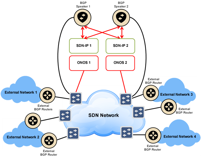
- The most fundamental building block is, of course, the SDN network. This is the network that is controlled by ONOS and will use SDN-IP to communicate with the outside world.
- The network is controlled by a cluster of ONOS instances (one or more).
- SDN-IP runs as an application on a subset of ONOS instances.
- External BGP routers are connected at the edge of the SDN network. These are routers belonging to other administrative domains that will peer with the SDN network through BGP. The SDN network needs to have direct (not routed) IP connectivity to each external router it needs to peer with.
- Inside the SDN network there are one or more BGP speakers. There are no specific requirements on the implementation of the BGP speakers - as long as they support both external BGP (eBGP) and internal BGP (iBGP) peering sessions. For our testing and deployments we use open-source software routers such as BIRD or Quagga. The internal BGP speakers peer in two different ways:
- Each BGP speaker must have at least one connection to the SDN data plane network. The BGP speaker will peer with external BGP routers over this connection using eBGP.
- Each BGP speaker also needs to peer with each SDN-IP instance using iBGP so it can relay routes to the SDN-IP instances. The connectivity for this peering must be out-of-band of the data plane.
BGP Peering Topology
There are no strict requirements on how the BGP topology should be set up, as long as each SDN-IP instance is able to receive all routes advertised to the SDN network through iBGP. In saying that, there are recommended deployment scenarios that we use and have tested thoroughly.
The following figure shows a BGP configuration example.
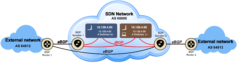
The icons show various nodes in the network and the lines show BGP peering sessions. Black lines are eBGP sessions between an internal BGP speaker and an external BGP router, and red lines are iBGP sessions amongst BGP speakers and SDN-IP instances.
Each external BGP router peers with one or more internal BGP speakers. SDN-IP does not currently support multihop BGP for external peering sessions, so each peering sessions must take place in the same subnet. Different peering sessions can be in different subnets however. In order to peer with external routers, the SDN network needs an IP address for each peering session. The IP addresses on the SDN network side are assigned to the BGP speakers so they can peer. It is not required that each internal BGP speaker peer with each external router, because the BGP speakers can redistribute routes between themselves using iBGP. However, for fully redundant peering with external networks, an external peer should have peering sessions with multiple internal BGP speakers. This can be seen in the figure where BGP Router 1 has a peering session to each internal BGP speaker.
Inside the network the BGP speakers peer with SDN-IP instances (running on ONOS) using iBGP. SDN-IP is a passive iBGP peer: it listens to BGP updates but it never advertises updates of its own. iBGP peering sessions within the network can be set up in multiple ways. The easiest way is to have a full mesh of iBGP peering sessions between the BGP speakers and the SDN-IP instances. This can be seen with the red iBGP peering sessions in the figure. In this way, all BGP nodes within the network can learn all the routes. Note it is not necessary (or possible) to have iBGP sessions between two SDN-IP instances, because the SDN-IP instances never advertise routes of their own.
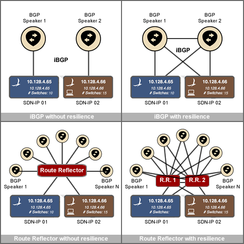
A variety of examples of different iBGP topologies are shown in the following figure.
ONOS-1.1 note: A subset of BGP Multiprotocol Extensions Capabilities (RFC 4760) is implemented: IPv4 and IPv6 unicast routes (AFI/SAFI). However, the receiving and processing of IPv6 routes has been tested only over IPv4 BGP peering.
Configuration
Please note the configuration file format has changed in ONOS 1.3 (Drake). For information on the older configuration format, please see an archived version of this page for the version of ONOS you are using.
SDN-IP requires some configuration so that it knows where the internal BGP speakers and external BGP peers are located, such that it can respond to ARPs correctly and program connectivity for the BGP traffic.
For each peering session that is set up, there will be a pair of IP addresses. One address is the address of the external peer, and the other address is the address the our internal BGP speaker uses. We require that these addresses are in the same subnet for now.
Network configuration file
SDN-IP's configuration uses the network config subsystem in ONOS. This system allows modifying configuration at runtime, however SDN-IP currently only supports reading static configuration defined at startup (we will add runtime config modification support soon).
Practically this means that SDN-IP config should be placed in the network-cfg.json file in your config directly, and it will be read in automatically at startup by the NetworkConfigLoader.
If you plan to deploy ONOS and SDN-IP manually you need to copy the configuration file in the config directory on each instance. This is located at KARAF_ROOT/../config, and the path is not currently configurable.
Otherwise, when using the ONOS cell mechansim to deploy an ONOS cluster, the config file can be placed in the ONOS_ROOT/tools/package/config directory, on the management node you use to deploy. Then, they will be automatically be copied to the correct location on the cell instances when the cluster is deployed.
JSON configuration format
The following code block shows an example of the JSON configuration format.
{
    "ports" : {
        "of:0000000000000005/4" : {
            "interfaces" : [
                {
                    "ips"  : [ "10.0.1.2/24" ],
                    "mac"  : "00:00:00:00:00:01"
                }
            ]
        },
        "of:0000000000000006/4" : {
            "interfaces" : [
                {
                    "ips"  : [ "10.0.2.2/24" ],
                    "mac"  : "00:00:00:00:00:03"
                }
            ]
        },
        "of:0000000000000007/4" : {
            "interfaces" : [
                {
                    "ips"  : [ "10.0.3.2/24" ],
                    "mac"  : "00:00:00:00:00:01"
                },
                {
                    "ips"  : [ "10.0.4.2/24" ],
                    "mac"  : "00:00:00:00:00:02"
                }
            ]
        },
        "of:0000000000000008/4" : {
            "interfaces" : [
                {
                    "ips"  : [ "10.0.5.2/24" ],
                    "mac"  : "00:00:00:00:00:02"
                },
                {
                    "ips"  : [ "10.0.6.2/24" ],
                    "mac"  : "00:00:00:00:00:03"
                }
            ]
        },
        "of:0000000000000009/4" : {
            "interfaces" : [
                {
                    "ips"  : [ "10.0.7.2/24" ],
                    "mac"  : "00:00:00:00:00:01"
                }
            ]
        },
        "of:0000000000000010/4" : {
            "interfaces" : [
                {
                    "ips"  : [ "10.0.8.2/24" ],
                    "mac"  : "00:00:00:00:00:03"
                }
            ]
        }
    },
    "apps" : {
        "org.onosproject.router" : {
            "bgp" : {
                "bgpSpeakers" : [
                    {
                        "name" : "speaker1",
                        "connectPoint" : "of:0000000000000001/7",
                        "peers" : [
                            "10.0.1.1",
                            "10.0.3.1",
                            "10.0.7.1"
                        ]
                    },
	                {
                        "connectPoint" : "of:0000000000000001/8",
                        "peers" : [
                            "10.0.4.1",
                            "10.0.5.1"
                        ]
                    },
	                {
                        "connectPoint" : "of:0000000000000001/9",
                        "peers" : [
                            "10.0.2.1",
                            "10.0.6.1",
                            "10.0.8.1"
                        ]
                    }
                ]
            }
        }
    }
}
There are two main sections to this file:
- The ports section that configures an interface on each switch port that connects to an external BGP router
- The bgp section that configures the internal BGP speakers that exist within the SDN network.
"ports" section
Here we configure an interface on each port that connects to an external BGP router. An interface is a set of addresses and other configuration that are logically mapped to the switch port, e.g. IP addresses, a MAC address, or a VLAN tag. These are the addresses that our network (i.e. our internal BGP speaker) is using to talk to entities outside the network. The concept is similar to how you would configure addresses or VLANs on an interface within Linux.
Each interface minimally needs one IP address and one MAC address. This information is used by the ProxyARP application so that it can respond to ARP requests from the outside world with the correct information. For SDN-IP, you need to configure the IP address that your network (and your internal BGP speaker) is using to peer with BGP peers outside the network. The MAC address you use for an interface should match the MAC address on the interface of the host that is running the internal BGP speaker that has that address. This is because BGP traffic from external peers is going to be forwarded to the BGP speaker, and if it has the wrong destination MAC address then the hosts's OS will drop the traffic.
If there is more than one internal BGP speaker having peering sessions on the same switch port, then it is possible to configure multiple interface sections on a single switch port (see port of:0000000000000008/4 in the example). This also works if you want to have different VLANs on the same port for different peering sessions.
"bgp" section
In this section we add configuration for each internal BGP speaker that exists in our network.
Each BGP speaker can have an optional name. This is not used by the system, but can be used by the operator to have a human-readable name for each speaker.
Each BGP speaker has a connnectPoint. This is the switch port in the network where the BGP speaker is physically plugged in.
In addition, each BGP speaker has a list of peer IP addresses which are the addresses of the peers which that BGP speaker is peering with. For each peer address that we configure here, there should be a corresponding address for our side of the connection that was configured in the "ports" section (see above). SDN-IP will determine which port the peer is connected at by finding an interface with an IP address in the same subnet. (This means that right now it's best not to use overlapping subnets for different interfaces. However it is fine to have to external peers in the same subnet if they are connected to our network at the same port). Once SDN-IP determines the peer-to-BGP-speaker association, it will install intents to allow BGP traffic to flow through the network between these two points.
SDN-IP component configuration
In addition to the network configuration described above, there is a separate configuration file for the SDN-IP software component. Currently there is one configurable parameter, the port that SDN-IP listens for incoming BGP connections on. If you wish to configure this parameter, place this file at KARAF_ROOT/etc/org.onosproject.routing.bgp.BgpSessionManager.cfg. Note that by default ONOS listens on TCP port number 2000 for incoming BGP connections, which is not the default BGP port number 179.
bgpPort=2000
BGP speakers
Each BGP speaker potentially has multiple peering sessions to different external networks. It is possible for these peering sessions to be on different IP subnets, which means each BGP speaker can potentially have multiple IP addresses it is peering on. These addresses must be configured in the network-cfg.json file, but they also need to be configured on the interfaces of the BGP speaker, so that it can receive packets sent to it on those addresses.
Running SDN-IP on ONOS
The first step is to get an ONOS system up and running, and you can read more about how to do this here: Installing and Running ONOS
Once ONOS is running, SDN-IP has an additional application dependency that it relies on to ensure ARP requests are resolved properly. This is the org.onosproject.proxyarp application that responds to ARP requests on behalf of hosts and external routers.
It's usually best to ensure this is loaded before starting SDN-IP, either by adding it to the ONOS_APPS variable in your cell file, or by loading it manually:
onos> app activate org.onosproject.proxyarp
Once this dependency has been satisfied, the SDN-IP application can be activated:
onos> app activate org.onosproject.sdnip
At this point, SDN-IP will start up, read its configuration and install intents in the network to establish connectivity for the BGP peering sessions. Then it will begin to receive routes, which are installed into the network using MultiPointToSinglePoint intents.
SDN-IP CLI commands
SDN-IP includes CLI commands that allow a user to monitor the state of the system. Each command is detailed below.
bgp-neighbors [-j|--json] [-n|--neighbor <neighbor>]
Shows the iBGP neighbors that have connected to SDN-IP. Each neighbor is an internal BGP speaker. Can be limited to show a specific neighbor.
bgp-routes [-j|--json] [s|--summary]
Shows best routes received from BGP peers, including BGP specific information.
bgp-routes [-j|--json] [n|–neighbor <neighbor>]
Shows all routes received from a particular BGP neighbor (even if those are not the best routes).
routes [-j|--json] [s|--summary]
Shows the routing table of SDN-IP. This should be mostly the same as the BGP routes, but may include routes from other sources.
Troubleshooting
A full running SDN-IP system has a lot of pieces that need to be correct before anything will work. When setting up a system for the first time or when things go wrong, it's best to go step by step to check each piece is in place.
Check SDN-IP is installed:
onos> apps -s | grep sdnip
*   4 org.onosproject.sdnip            1.3.0.SNAPSHOT SDN-IP peering application
The little * in the 1st column means SDN-IP is activated. If it's not there, try activate it again.
Check whether the external routers can resolve ARP properly. If they can't resolve ARP, then look in the addresses.json file and check that the address configuration is correct.
Check the BGP peering sessions are established with the internal BGP speakers. If the peering sessions are not established, it may be that the sdnip.json configuration is wrong. If it seems to be correct, check the configuration of the BGP peers.
Check the configuration files are in the correct directory.
Next, check that the internal BGP speakers are peering with ONOS correctly:
onos> bgp-neighbors
You should see a list of internal BGP speakers. If not, check that the connectivity is OK and the BGP configuration in the BGP speaker is correct.
Then, check if ONOS receives the expected routes:
onos> routes
If the routes are not received, check if the internal BGP speaker has received the routes and advertised them to ONOS.
In addition, you could use the following command to see BGP-specific information about the received routes:
onos> bgp-routes
Once the routes are received, ONOS will start to install MultiPointToSinglePoint intents for each route. You can check this is correct by looking at the number of MultiPointToSinglePoint intents in the intent summary. It should be the same as the number of routes, and all intents should move to the INSTALLED state before long.
onos> intents -s
Once intents are installed, there should be transit connectivity through the SDN network.
Questions? Comments? Problems?
Please let us know via the onos-deploy mailing list. Details about ONOS mailing lists can be found here: Mailing Lists
We really welcome your help to ensure the code and documentation are clear and informative, so let us know if you have and issues.
4 Comments
Larkland Morley
This would be a very useful use case if Host within the SDN network can communicate to the outside through these routers. Is there any plans to have this soon?
Luca Prete
Hi Larlkland,
Sure! It's in the plan for the February release. We understood it's an important limitation. You can see more details on future release at https://wiki.onosproject.org/display/ONOS/Upcoming+Release+Contents
Larkland Morley
I will be playing with the software soon. Does it currently support virtual router capabilities within the SDN network? Meaning L2/L3 Forwarding.
leon liu
Hi ,
I try to deploy manually, but i met below issue, below dir is not exists. Where should i put the address.json and sdnip.json files?
"This is located at
KARAF_ROOT/../config, and the path is not currently configurable."Thanks!