Due to a ransomware attack, the wiki was reverted to a July 2022 version. . We apologize for the lack of a more recent valid backup.
Team
| Name | Organization | Role | |
|---|---|---|---|
| Dimitris Mavrommatis | ONF / Foundation for Research and Technology - Hellas (FORTH), Institute of Computer Science, INSPIRE group | Lead Developer | dimitris@opennetworking.org |
| Sanjana Agarwal | ONF | Lead Developer | sanjana@opennetworking.org |
| Sarabjot Singh | XRAN.org | Project Coordinator | sarabjot.singh@xran.org |
Overview & goals
The xRAN controller implements the control plane functionality interfacing with the eNodeB data-plane functionality through the xRANc-API. The control plane functionality will include, but is not limited to, UE Admission Control, Radio Bearer Admission and Modification, Handoffs, and Load Balancing, Inter-cell Interference Coordination etc.

RAN Controller Constituents
Radio-Network Information Base (RNIB)
- A graph of physical/logical network entities
- Control applications read and write to R-NIB using NorthBound Interface (NBI)
Network Topology (NT) Database
- LTE cell configuration parameters like cellIDs, latitude, longitudes, bands, azimuth, etc.
- Interfaces with R-NIB to provide spatio-temporal context
Functions
- Call/Bearer Admission Control
- Load Balancing and Policy Enforcement
- Radio Link Monitoring
- Slice Enforcer
R-NIB: Overview
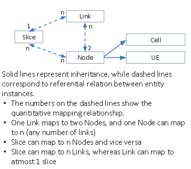
RNIB is a graph of physical/logical network entities within the network topology:
- Cell: eNBs, gNBs, WLAN AP, etc.
- UE: Smartphone, Car, etc.
- Slice: a virtual network within
- Link: air interface between eNB and UE, self backhauling link
Maintained as a relational database
Controller Routines
R-NIB consistency/integrity routine:
- Makes sure that there is only one link of type serving/primary involving a given UE
- Makes sure the mapping between context IDs <->IMS <-> RAN ID is consistent
Configuration routine:
- Periodically sends CellConfigRequest to Cells that have the Cell/Conf set to empty, until it gets populated
- Periodically sends UECapabilityEnquiry for UEs that have the UE/Capability field empty
Measurement routine:
- Sends XRANC_L2_MEAS_CONFIG once for each cell whose Conf has been set.
- Sends XRANC_RX_SIGNAL_MEAS_CONFIG, for UEs whose MeasConfig is not set.
Admission control:
- Responds with UEAdmissionResponse to UEAdmissionRequest depending on admission control policy
- Responds with BearerAdmissionResponse to BearerAdmissionRequest depending on bearer admission policy
Slice Enforcement:
- Policy intents to southbound messages
Functions Details
Handover

The call flow is shown in the following figure, where the objective is to move UE 2 to Cell 2. The steps undertaken are shown below:
Application issues a PATCH/POST command for the intent to modify/create the link{2,2} to be of type serving/primary
R-NIB consistency routine interprets the above PATCH/POST as a handover since there can not be more than one primary serving links terminating at the same UE
Controller sends the HORequest with ecgi-t set to that of Cell 2 and ecgi-s set to that of the cell which currently has the serving/primary link to UE 2. CRNTI is set to RAN ID of UE 2.
Upon getting HOComplete from cell 2, controller updates link{2,2} to be of type serving/primary, UE 2’ RAN-ID with new CRNTI from cell2, link{1,2} to be non-serving.
The new ContextIDs obtained from UEContextUpdate preceding HOComplete for this UE are used to populate the new ContextIDs
PRB Restriction
Cell Specific
The figure below shows an example call flow, where the objective is to restrict the PRB used on the two cells
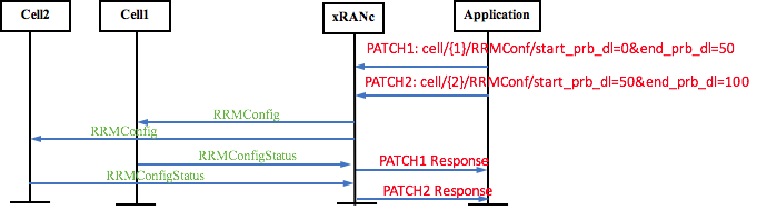
The steps associated with the call flow are:
Applications express the intent to modify the RRMConfiguration of cell 1 using PATCH (say)
Controller sends a RRMConfig message to the corresponding ECGI using the PATCH request parameters and CRNTI field blank
R-NIB is updated and PATCH response delivered after receiving the RRMConfigStatus from the corresponding cell
Link Specific
The following call flow shows restriction based on particular links only


The steps associated with the call flow are:
Applications express the intent to modify the RRMConfiguration of link{1,1} to using PATCH (say)
Controller finds the CRNTI and ECGI connected by this link
Depending on the eNB support it sends RRMConfig or xICICConfig on the B1 interface
The message constituents are formed based on the PATCH request parameters and ECGI, CRNTI corresponding to that link
In case using the RRMConfig message, R-NIB is updated and PATCH response delivered after receiving the RRMConfigStatus from the eNodeB
Programmable CA Deployment
Note: This functionality is only applicable to cells CA supported indicated using CellConfigReport/featureSupportList

The steps associated with the call flow are:
Applications uses PATCH/POST to modify/create the link{2,1} of type serving/secondary/ca.
Check if the UE is capable of CA by looking up the existence of “ca” under UE/Capability, if not reply in error.
Controller populates the field of ScellAdd as follows:
ECGI = ecgi of the primary cell of the UE in question
CRNTI = CRNTI of the UE at the primary cell
scells-prop:
PCI-ARFCN of the cell corresponding to link{2,1}
cross-carrier-sched-enable : UE/Capability/ca/crossCarrierSched
ca-direction: dl
deact-timer : 10000
Upon receiving the ScellAddStatus/status set to success for the PCI-ARFCN of link{2,1}’s cell in scells-ind, the change is reflected in R-NIB and POST/PATCH response given to application.
Slicing
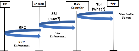
Key steps:
App uploads a slice profile through NBI at RAN controller
RAN controller enforces slice primitives through SBI
eNodeB implements instructions on the SB

The steps associated with the call flow are
Application uploads a slice profile. R-NIB consistency routine checks the slice attributes and the slice enforcement routine checks the intents. If both the checks pass
Slice Enforcement Routine interprets the presence of ResourceReservation as an intent to send the RRMConfig/XICICConfig for the involved links.
The available PRBs range for reservation are found at each cell by taking a diff of the reserved PRBs of the existing links
Using the absolute PRBs required by the slice enforcement routine, the appropriate range is obtained and sent on RRMConfig/XICICConfig.
Example: if prbs from 0 to 20 are already reserved at Cell 1 and prbs from 0 to 40 at Cell 2, then link{1,1} has to be reserved prbs in range 21 to 70, and link{2,3} has to be reserved prbs in range {41,90}. Remaining links link{1,2} and link{2,4} have to moved to remaining prbs on the cells, like link{1,2} to be reserved 70 to 99, and link{2,4} to be reserved to {90,100}.
Controller Implementation Details
Southbound Interface
There is a SCTP netty server socket to listen for CELL connections on a port specified in the configuration file. The communication between the Controller and the CELL is using ASN.1 protocol with BER encoding. Each packet consists of a header and a body that are standarized by the xRAN organization:
- The header carries the specification version identifier and the type of the packet.
- The body depending on the type of the packet carries the data.
Configuration file includes a list of acceptable CELLs with some identifiers to avoid malicious connections.
Northbound Interface
A REST based framework is used to handle the northbound requests. It supports GET, POST, PATCH, DELETE for NODE, CELL, LINK and SLICE entities. The events that ca be triggered from Northbound can be:
UE Handover
PRB Restriction for CELL/LINK
Programmable CA Deployment
- Slicing
Network State
UEs have the State attribute associated with them
ACTIVE: Default state when UE is created
IDLE: Set upon receiving a release packet from primary cell
Links have a Type attribute associated with them
Serving/Primary: Only one link per UE can be primary
Serving/Secondary: Used to increase UE throughput
Non-serving: Inactive links that we gather measurement reports and can be changed to primary or secondary links