Due to a ransomware attack, the wiki was reverted to a July 2022 version. . We apologize for the lack of a more recent valid backup.
...
While legacy technologies require the manual configuration of multiple devices in the network, VPLS tries to make the process easier for network operators.
The current model expects that hosts to be connected together (any L3 device), sends into the network tagged packets (VLAN Ids)Hosts that get connected together can send in either untagged or VLAN tagged traffic, using either the same or different VLAN ids.
The User Guide assumes:
You already have knowledge on how ONOS generally works;
ONOS has been already installed OR or there’s a management machine ready to push bits to some target machines;
Different hosts have been directly attached to the OpenFlow data plane and they send out packets using none or some (same or different) VLAN Ids.
Starting VPLS
VPLS can set to be installed and configured:
...
Manually, through the ONOS Command Line (CLI), typing "app activate org.onosproject.vpls";
Automatically at ONOS start up, adding the application name "vpls" to the list of apps to be started automatically, in the cell file. Specific startup details can be defined in its own the cell file , on the management machine, before pushing the ONOS bits. See example below:Below, an example is reported.
| Code Block | ||
|---|---|---|
| ||
# Basic VPLS topology export ONOS_NIC=192.168.56.* export OCI="192.168.56.101" export OC1="192.168.56.101" export OC2="192.168.56.102" export OC3="192.168.56.103" export ONOS_APPS=drivers,openflow,vpls export ONOS_GROUP=sdn export ONOS_SCENARIOS=$ONOS/tools/test/scenarios export ONOS_TOPO=vpls export ONOS_USER=sdn export ONOS_USE_SSH=true export ONOS_WEB_PASS=rocks export ONOS_WEB_USER=onos |
...
VPLS relies on the ONOS network configuration subsystem, which is by default distributed on all ONOS nodes and shared by all ONOS applications.
In order to configure have a VPLS working, two things need to be donehappen:
Configure two Two or more interfaces need to be configured
At least one Configure one or more VPLS that associate the above interfaces together needs to be configured together
The goal of the configuration process is to define what attachment points the hosts are connected to (so which DPID , twhich and which ports), and to associate them under the same overlay network, a VPLS. This will essentially determine what hosts should talk one each other (communicate together, and which don’t).
Both the the interfaces interface and the VPLS configuration itself configurations can be applied either:
Creating Defining a special network-cfg.json configuration file on the management machine, in $ONOS/tools/package/config, before pushing the ONOS bits to the target machines. In this case -while deploying- the network-cfg.json file will be copied over the target machines and parsed; this way is very convenient while developing, but it's not suggested for production deployments
Pushing the same network-cfg.json file at Pushing a JSON file at run-time, after ONOS has started, using the specific REST API;
From the ONOS CLI, using the interface commands.
Configuration file format and syntax
APIs. This can be done from the management machine, using the tool onos-netcfg (i.e. onos-netcfg {$IP} {NET_CFG_FILE})
From the ONOS CLI, using the interface and VPLS commands
Configuration file format and syntax
Let’s assume the following scenario:
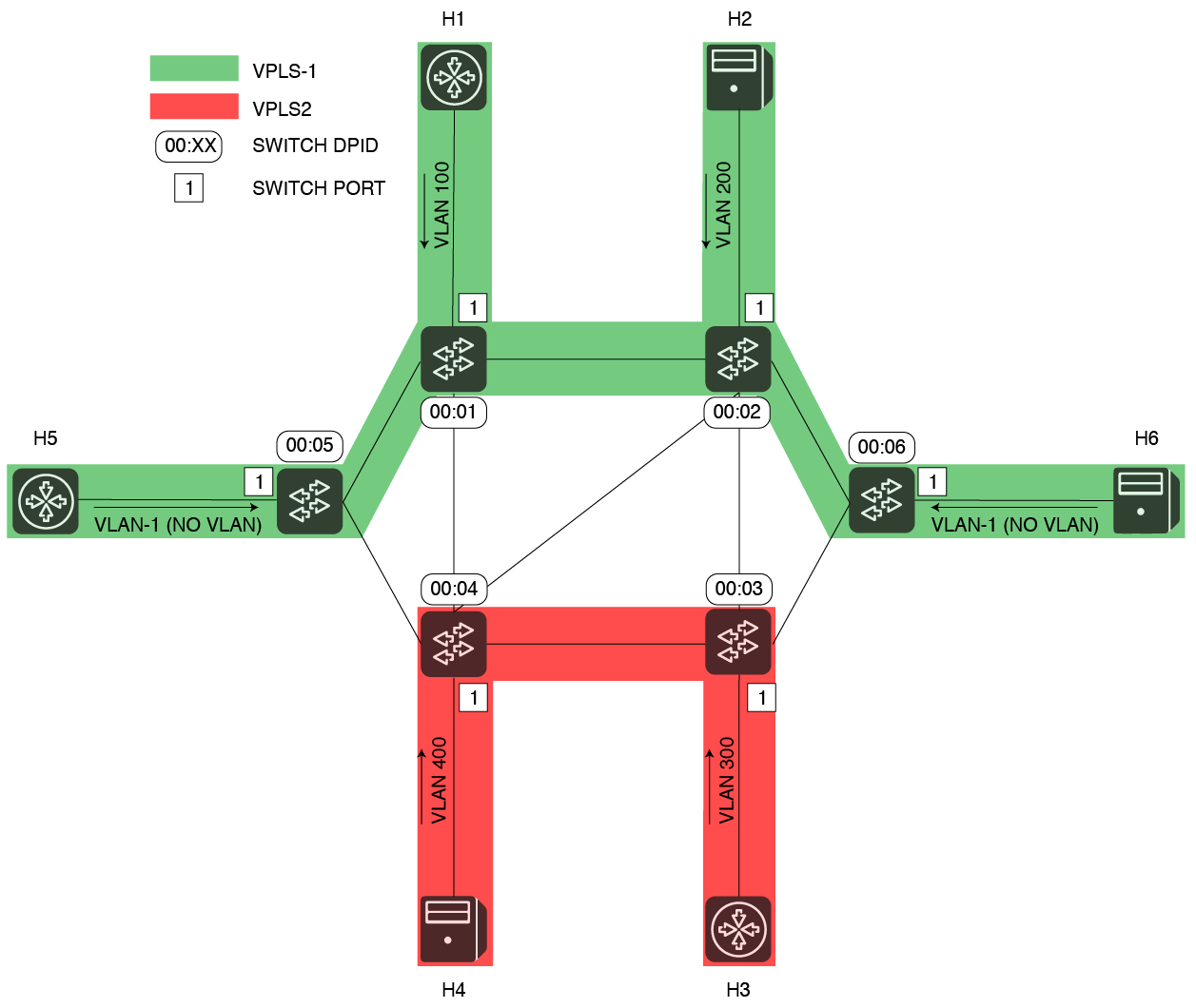
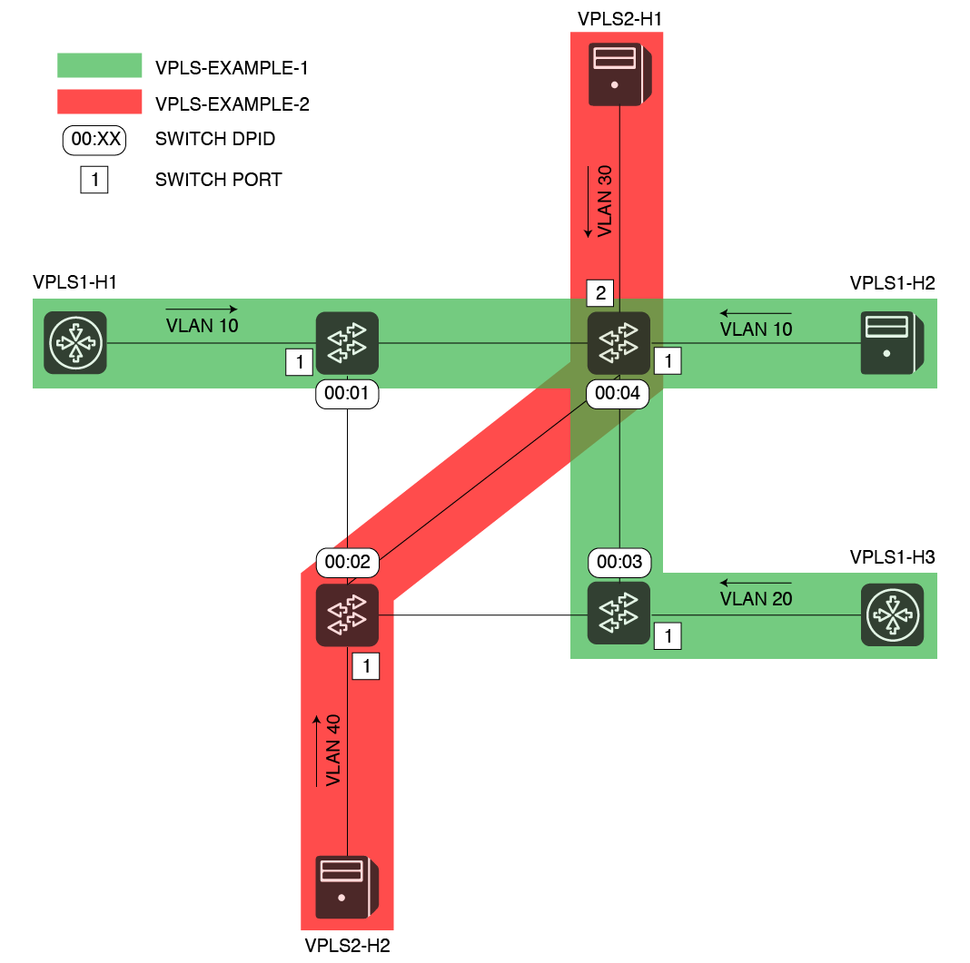
In this example, five hosts are sending in tagged packets with different VLAN Ids. Two networks will be created, one called VPLS-EXAMPLE-1 ( VPLS1 ) -in green, the second one called VPLS-EXAMPLE-2 ( VPLS2 ) -in red. Three Four hosts will be grouped and connected in VPLS1, while other two will be associated to VPLS2.
Hosts are grouped by VPLS in the following table:
VPLS name | VLAN Id | Interface Name | OF Switch DPID | OF Port Number |
VPLS1 | 100 | h1 | 0000000000000001 | 1 |
VPLS1 | 200 | h2 | 00000000000000040000000000000002 | 1 |
VPLS1 | -1 (no VLAN) | h5 | 0000000000000005 | 1 |
| VPLS1 | -1 (no VLAN) | h6 | 0000000000000006 | 1 |
VPLS2 | 300 | h4h3 | 00000000000000040000000000000003 | 21 |
VPLS2 | 400 | vpls2h2h4 | 00000000000000020000000000000004 | 1 |
In order to configure what has been described above, the following configuration should be pushed to ONOS (either before or after VPLS has been started).
...
The same result can be achieved at run-time, using the interface configuration and VPLS CLI commands as follows (see section "CLI syntax" for more details):
| Code Block | ||
|---|---|---|
| ||
onos> interface-add -v 10100 of:0000000000000001/1 vpls1h1h1 onos> interface-add -v 10200 of:00000000000000040000000000000002/1 vpls1h2h2 onos> interface-add -v 20300 of:00000000000000030000000000000004/1 vpls1h3h3 onos> interface-add -v 30400 of:00000000000000040000000000000002/21 vpls2h1h4 onos> interface-add of:0000000000000005/1 h5 onos> interface-v 40add of:00000000000000020000000000000006/1 vpls2h2h6 onos> vpls-add create VPLS1 onos> vpls- add-iface VPLS1 vpls1h1h1 onos> vpls- add-iface VPLS1 vpls1h2h2 onos> vpls- add-iface VPLS1 vpls1h3h5 onos> vpls add-iface VPLS1 h6 onos> vpls set-encap VLPS1 VLAN onos> vpls-add create VPLS2 onos> vpls- add-iface VPLS2 vpls2h1h3 onos> vpls- add-iface VPLS2 vpls2h2h4 |
As soon as two or more interfaces are added to the same VPLS network, intents to manage broadcast will be installed.
As soon as two or more hosts connected to the same VPLS will get discovered by ONOS (and VPLS), intents to manage unicast traffic will be installed.
For more details on the VPLS architecture, internal workflow and intents used, please visit the VPLS Architecture Guide.
...
Demo topology
Would you like to give VPLS a try, but it's too hard and long bringing up an entire network with hosts sending in packets on different VLANs? The mininet (python) file attached gives you an example of how to simulate a similar network. Just modify the file, creating the topology you like and letting Mininet point to your controller IP address.
CLI syntax
We made available a default topology file in ONOS for you!
The topology file is under $ONOS_ROOT/tools/test/topos. It consists of three files:
- The Mininet topology file
- The network-cfg.json ONOS configuration file
- The receipe file, to check that when the topology is instantiated the number of devices, hosts and links matches the expectations
You can just take these files as examples for your topologies / configurations, or you can use them automatically along with the tool stc net-setup, which makes very convenient to deploy ONOS and Mininet together in a couple of commands.
Using the topology file along with stc net-setup is very simple. Just few steps:
- Create one mininet machine and one or more ONOS target machines (ready to receive the ONOS bits). The mininet machine should have the same username and password of the ONOS machine(s) and you should be able to run on it as well as sudoer without password
- Define your cell file. Add to it the following variable: OCN=XXX.YYY.WWW.ZZZ, where XXX.YYY.WWW.ZZZ is the IP of your Mininet machine
- After you have loaded your cell file, run the command topo vpls. This will tell stc what topology to use.
- Now run stc setup && stc net-setup. This will first deploy ONOS on the remote nodes (stc setup). It will then deploy the Mininet topology and apply the related ONOS configuration.
- You will be able to access your mininet machine directly from the management machine,
CLI syntax
VPLS allows to define networks and attach or detach interfaces to them, also by command-line. There is also the option of cleaning all the state of the application for a clean start. Details on the CLI operations are detailed below:The applications allows to define and configured VPLSs also from a CLI. The paragraph below reports details about the CLI command syntax.
| Code Block | ||
|---|---|---|
| ||
# AddsCreates a new network onos> vpls-add create {$VPLS_NETWORKNAME} # RemovesDeletes an existing network onos> vpls- del {$VPLS_NETWORKNAME} # ShowsLists the configured VPLSs onos> vpls list of networks onos> vpls-list VPLS2 VPLS1 # Shows the list of attached interfaces (for a given network) or all the list of networks and interfaces in each of them (if no network is provided) onos> vpls-show [$VPLS_NETWORK] VPLS2: interface=[vpls2h1, vpls2h2] VPLS1: interface=[vpls1h1, vpls1h2, vpls1h3] # Encapsulation (optional) onos> vpls-set-encap $VPLS_NETWORK Configured VPLSs ---------------- VPLS1 VPLS2 # Shows the list configured VPLSs, including their interfaces and the encapsulation type in use. If a VPLS name is specified, only the details for that VPLS are returned. onos> vpls show [$VPLS_NAME] Configured VPLSs ---------------- VPLS name: VPLS1 Associated interfaces: [h1, h2, h5, h6] Encapsulation: NONE ---------------- VPLS name: VPLS2 Associated interfaces: [h3, h4] Encapsulation: VLAN ---------------- # Sets the encapsulation type for a VPLS onos> vpls set-encap {$VPLS_NAME} {VLAN|MPLS|NONE} |
| Code Block | ||
|---|---|---|
| ||
# Adds an existing interface (in netcfg) to an existing networkVPLS onos> vpls- add-iface {$VPLS_NETWORKNAME} {$INTERFACE_NAME} # Removes an existing interface from an existing networkVPLS onos> vpls-del rem-iface {$VPLS_NETWORKNAME} {$INTERFACE_NAME} |
| Code Block | ||
|---|---|---|
| ||
# Cleans the status of the VPLS application (i.e., removes networks, detaches interfaces and withdraws intents) onos> vpls- clean |
Issues and Troubleshooting
...