Due to a ransomware attack, the wiki was reverted to a July 2022 version. . We apologize for the lack of a more recent valid backup.
Overview
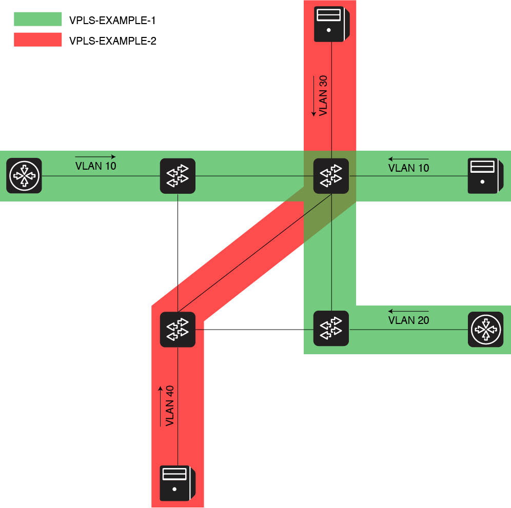
Virtual Private LAN Service (VPLS) is an ONOS application that allows the creation of enables operators to create L2 broadcast overlay networks on-demand, on top of OpenFlow infrastructures.
The application connects into overlay broadcast network networks hosts connected to the OpenFlow data plane, sharing the same VLAN Id.
...
In order to let VPLS establish connectivity between two or more hosts, two different things need to happen:
A VPLS needs to be defined
At least two interfaces
with the same VLAN Id need to be configured in the ONOS interfaces configuration
;At least two interfaces need to be associated to the same VPLS
At least two hosts need to be connected to the OpenFlow network. Hosts participating to the same VPLS can send in packets tagged with the same VLAN Ids, different VLAN Ids, no VLAN Ids at all
When conditions 1 gets , 2 and 3 are satisfied, any host a) hosts attached to the ports where the interfaces have been configured, b) sending in traffic using the same VLAN that has been configured, VPLS will be able to send in and receive broadcast traffic (i.e. ARP requests) to the other hosts in the same overlay networkrequest messages). This is needed to make sure that all hosts get discovered properly, before establishing unicast communication.
When 1 and 2 get 4 gets satisfied -meaning that ONOS discovers as hosts with a MAC address and a VLAN, at least two hosts of the hosts configured same VPLS- unicast communication between the hosts discovered on that specific overlay network.
General workflow
The VPLS workflow can be grouped in two main functions:
Collect information about the configuration and hosts attached
Install the flows needed to let the hosts communicate
Information collection
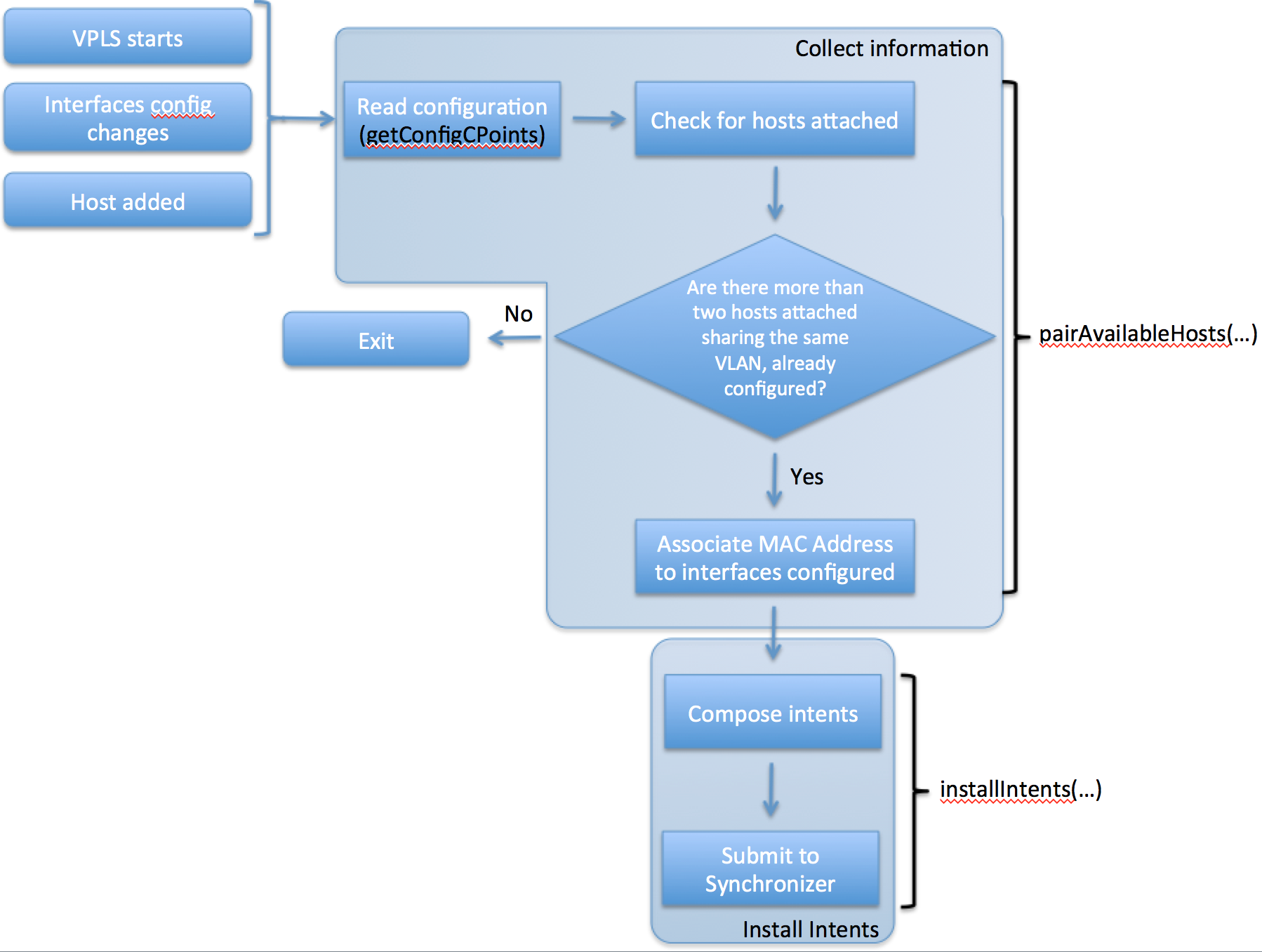
Information collection is grouped in two main functions called in sequence, that represent the main steps that the application performs at each operational cycle:
getConfigCPoints(...): it parses the ONOS interfaces configuration, looking for two or more attachment points with interfaces configured with the same VLAN Id and with no IP addresses configured. Looking for interfaces without an IP addresses means looking for pure Layer 2 interfaces and it’s done to don’t conflict with Layer 3 ONOS applications that use the same configuration mechanism. The interfaces found are grouped by VLAN Id (in a HashMap) and returned to the next method, pairAvailableHosts(...).
pairAvailableHosts(...): it parses (if not null) the data structure received from getConfigCPoints(...) and for each interface found finds hosts in the Host Service matching with the interfaces configured. If hosts are found, the original data structure is modified: the MAC addresses of the hosts found is bound to the related interfaces discovered in the configuration. The final data structure is then returned.
Intent installation
...
is established.
Components:
VPLS contains several components:
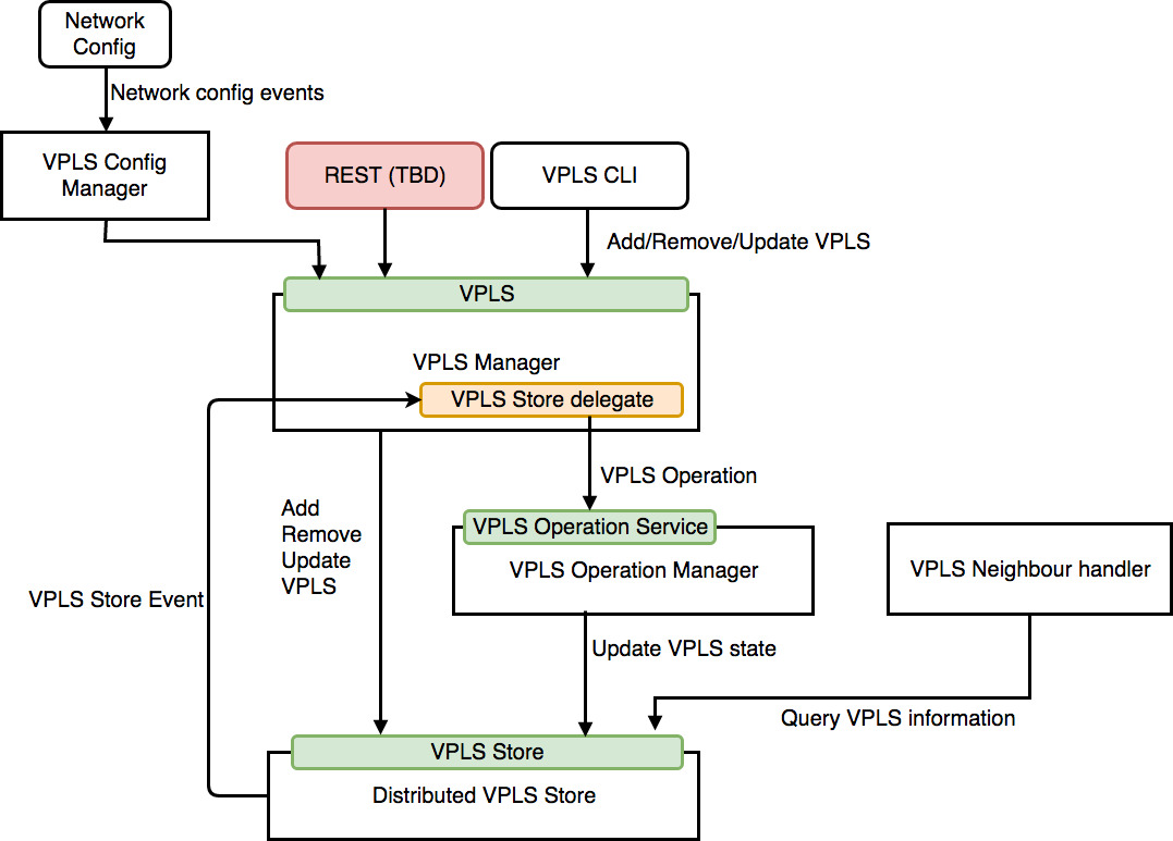
VPLS (VPLS Manager):
- Provides public API for managing virtual private LANs.
- The API provides create/update/read/delete (CURD) functionality, helps other application to interact with VPLS Store and VPLS operation service.
- Handles host events to attach/detach hosts to a virtual private LAN
VPLS Store Delegate (in VPLS Manager):
Handles VPLS store events, it will generate new VPLS Operation according to store event type and VPLS status.
Also, after it generate an operation, it will send to VPLS Operation Service directly.
VPLS Operation Service(VPLS Operation Manager):
Manage any operation(modification) of any VPLS.
Convert VPLS operations to sets of Intent operations.
Provide correct order of Intent operations.
Update VPLS status to store when finished/failed VPLS operation.
VPLS Store (Distributed VPLS Store):
Stores all VPLS information
Push all VPLS information to network config system
VPLS Config Manager:
Handles network config update event
Optimize changes from VPLS network config event and invoke VPLS API
VPLS Neighbour Handler:
Handles neighbour messages of any VPLS from any interface
VPLS REST API (Work in progress):
Provides REST API to control VPLS
General workflow
VPLS can be changed by these ways:
Host event (host added or removed)
Network config modification
VPLS command
- VPLS REST API
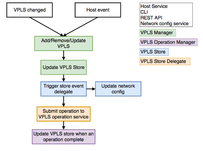
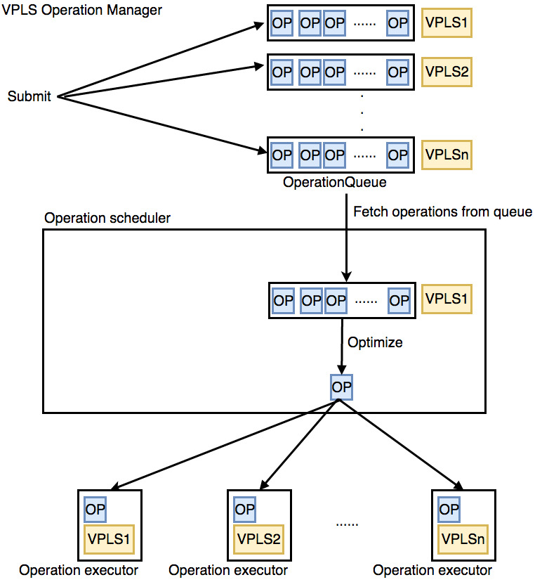
VPLS Operation Service
- When a new VPLS operation generated and submit to VPLS operation service the operation will be queued.
- An operation scheduler will take batches of operation for multiple VPLS, if there exists multiple operations to process, it will optimize operations to a single operation.
- For every operation to be process, the scheduler will put the operation into operation executor and add success and error consumer to it.
- For success consumer, it will update VPLS state according to previous state (e.g. ADDING -> ADDED)
- For error consumer, will change the state to FAILED.
VPLS Operation Executor (Intent installation)
The VPLS Operation Executor will generate different Intent operations for different operation type (add, remove or update VPLS).
For ADD operation, executor will generate two types of Intents:
Single-Point to Multi-Point intents Intents for broadcast traffic, from any ingress point to every egress point, configured in the same VLANVPLS.
Multi-Point to Single-Point intents Intents for unicast traffic, from every egress point to any ingress point in the same VLAN.
Functions above are grouped in a unique method called setupConnectivity(). The method is called
At the application startup;
Every time the interface configuration gets updated;
As soon as new hosts join the network and get discovered.
...
VPLS.
- See Traffic provisioning and intent requests chapter below for more information.
For REMOVE operation, the executor will find every intents related to the VPLS (by Intent key) and remove them.
For UPDATE operation, two situation will be considered:
Interfaces updated: will reinstall all Intents related to this VPLS.
Hosts updated: will remove or add new unicast Intent only.
Provide correct ordering of Intent installation
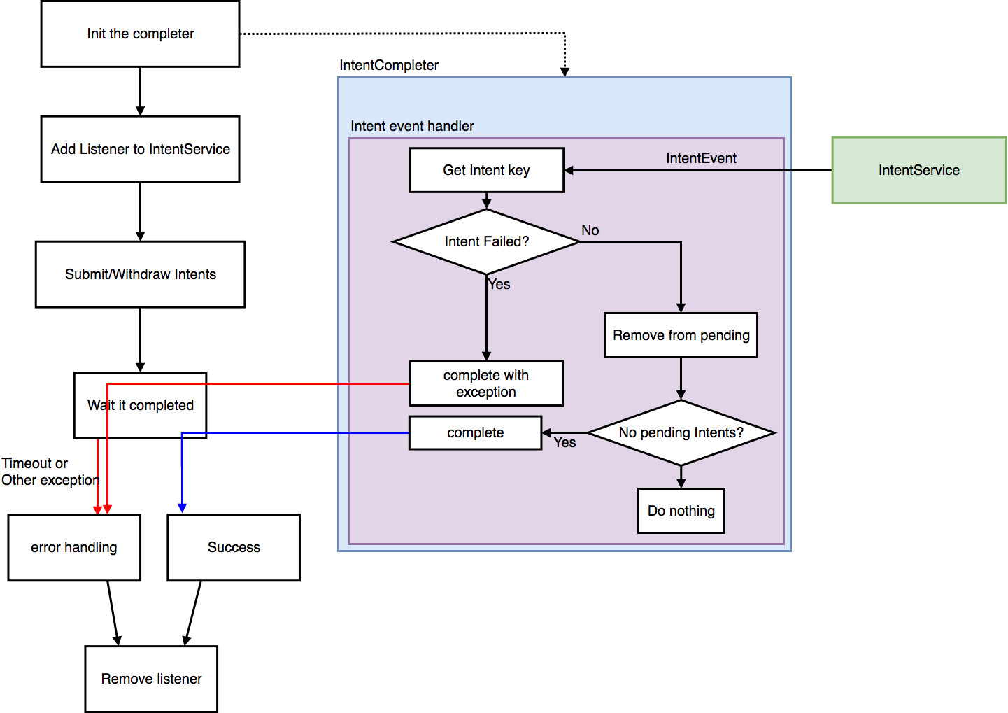
To resolve race condition issue (install after withdraw Intents), the executor uses IntentCompleter to wait Intent installation process.
An IntentCompleter is a kind of IntentListener, initialize by Intent keys we need to wait, then register as listener to the IntentService and do Intent operations (submit, withdraw)
After that, invoke “complete” method from the IntentCompleter, it will wait until all Intents finished or timeout exceed.
Network configuration, interface configuration and hosts listeners
VPLS has listeners for two three event types:
Interface configuration updates: each time a node in the interface configuartion configuration is added, updated or deleted, for example pushing the network-cfg.json JSON configuration file or through CLI. Interfaces The Interface configuration is filtered to consider only the interfaces with VLANs configured, but not IP. Also, informations are considered by VPLS, only if two or more interfaces are correctly configured, using the same VLAN Idwith no IPs (to avoid to conflict with Layer3 applications, such as SDN-IP).
VPLS configuration updates: each time a node in the VPLS configuration is added or updated or deleted, for example pushing JSON file or through CLI.
Host added / Host updated: each time a host joins the network, meaning a new host get gets physically connected to the OpenFlow data plane and start to send in starts sending ARP packets into the network ARP packets. The Host Service will discover the host (with a MAC address, possiblly possibly a VLAN , and possibly one or more IP addresses). VPLS listens for Host added / updated / removed events and filters hosts that are attached to attachment pointsthe OpenFlow switches, and use VLANs, according to what has been configured in the interfaces section..
Traffic provisioning and intent requests
The ONOS Intent Framework is used to provision both broadcast and unicast connectivity between the edge ports of the OpenFlow network, where hosts are attached to. Using the Intent Framework intent framework abstraction allows to mask the complexity of provisioning single flows on each switch and failover do error recovering in case failures happen.
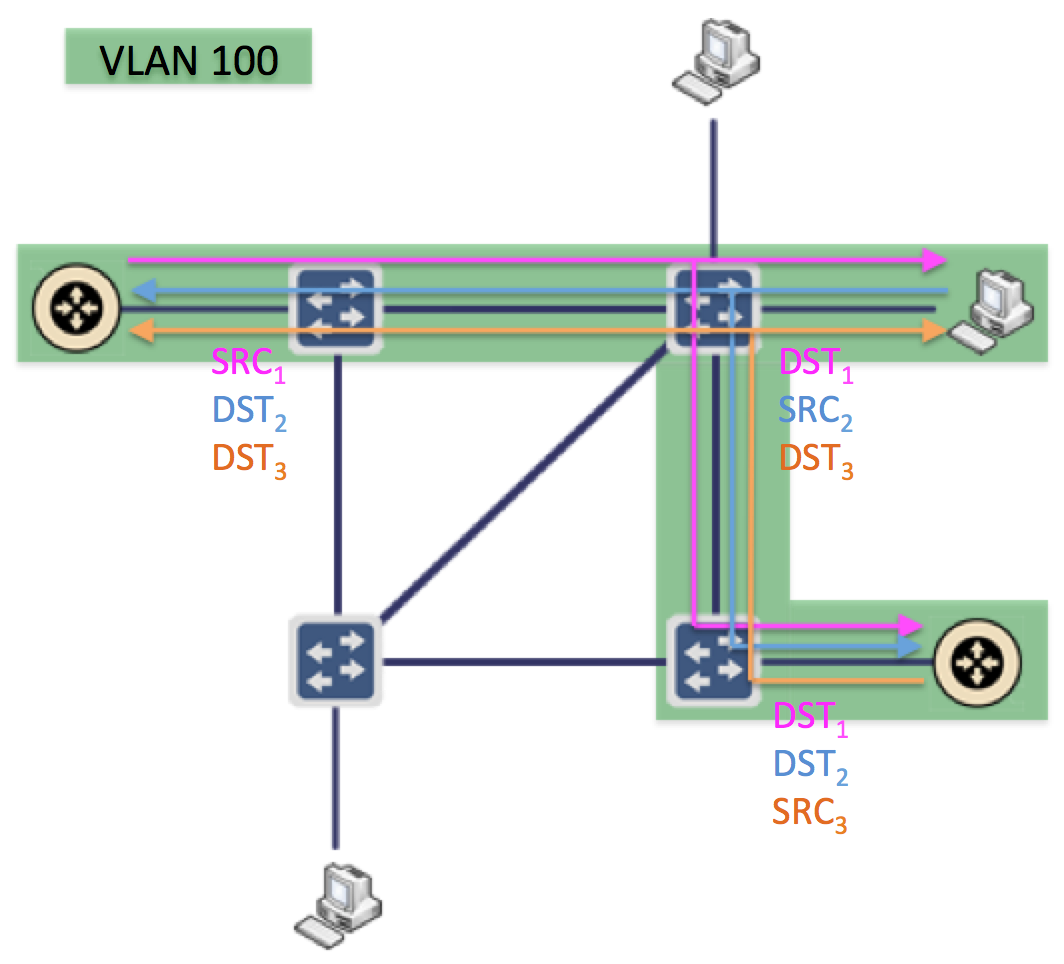
Broadcast traffic: single-point to multi-point intents
Broadcast connectivity is provisioned through single-point to multi-point intents. Within the same VLANVPLS, for each host (source of the broadcast traffic), a single-point to multi-point intent is instantiated.installed.
The (single) ingress point of each intent is the edge port where the source host (for that intent) is connected to. The egress points are any other edge port where destination hosts associated to the same VPLS, are connected to.
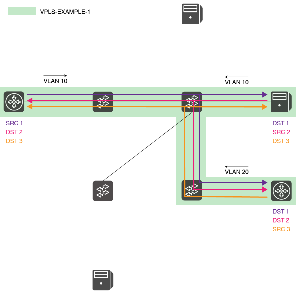
The intent ingress selector is defined using the edge in-port, the Intents match on destination MAC address FF:FF:FF:FF:FF:FF (broadcast Ethernet address) and on the VLAN Id shared by the overlay network. As treatment, the traffic is carried through the best-path to all the other edge ports configured to use the same VLAN Id.The (single) ingress point of each intent is the edge port where the soruce hosts (for that intent) is connected to. The egress point is any other edge port where destination hosts (for that intent) with the same VLAN Id, are connected toof the source host (in case the interface associated has a VLAN Id associated), according to what has been defined in the interface configuration. The egress selectors are defined as the ingress selector (broadcast Ethernet address), but with the VLAN Id of the destination hosts (in case destination hosts have VLANs configured). The intent framework automatically performs the VLAN Id translation (translation, popping, pushing) at the egress as needed, before the traffic is sent to the destination hosts. The traffic is carried through the best-path - according to the PCE installed - to all the edge ports associated to the same VPLS.
Assuming N edge ports have interfaces configured within associated to the same VLAN IdVPLS, N single-point to multi-point intents for broadcast will be installed.
Intents for Broadcast traffic get generated, reguardless regardless the hosts have been discovered or not. This is done since often hosts won’t be able to send traffic into the network (so get discovered by the Host Service) before ARP requests reach them and they reply to them with an ARP reply.
Unicast traffic: multi-point to single-point intents
Unicast connectivity is provisioned through multi-point to single-point intents. Within the same VLANVPLS, for each host (destination of the unicast traffic), a multi-point to single-point intent is instantiatedinstalled.
Intents match on unicast destination MAC of the source host and on the VLAN Id shared by the overlay network. As treatment, the traffic is carried through the best-path to the source edge port.
The (multiple) ingress points of each intent are the The egress point of each intent is the edge port where the destination host is connected to. The ingress points are any other edge ports where the destination hosts (for that intent) source hosts associated to the same VPLS, are connected to. The egress point is the source edge port where the source host (for that intent) within the same VLAN Id, is connected to
At each ingress, the intent ingress selector is defined using the edge in-port, the MAC address of the destination host, and the VLAN Id of the source host (in case the source interface has a VLAN Id configured), according to what has been defined in the interface configuration. The egress selector is defined as the ingress selectors (matching on the destination MAC address), but with the VLAN Id of the destination host (in case the interfaces associated to the destination hosts have a VLAN Id configured). The intent framework automatically performs the VLAN Id translation (translation, popping, pushing) at the ingress as needed, before the traffic is sent through the core. The traffic is carried through the best-path - according to the PCE installed - to all the edge ports associated to the same VPLS.
Assuming N edge ports have interfaces configured within associated to the same VLAN Id and N related hosts have been discovered VPLS, N multi-point to single-point intents for unicast will be installed.
...

Intents for Unicast traffic get generated only if:
Two or more interfaces sharing the same (with a VLAN Id (configured and with no IPs) are configured and associated to the same VPLS;
Two or more hosts attached to the interfaces configured send packet packets into the network sharing the same VLAN Id and on through the physical ports (configured above), and get discovered by the ONOS Host Service,
The reason for the second condition is that intents for unicast (see above) match on the MAC address of the hosts connected, which is doesn’t get configured by the operator, but instead provided by the host service after the host gets discovered.
Current Limitations
At the present stage:
...
VPLS leader election
VPLS runs on top of ONOS as a distributed application. VPLS applications share their status and use common data structures. ONOS makes sure they remain in synch.
At the beginning, the VPLS operation manager from each ONOS instance will send a request to LeadershipService to make sure which instance is the leader of VPLS application.
Only the leader node can execute VPLS operation and install Intents now.
Known limitations
At the current stage:
Only VLAN tags can be used , no MPLS;
Hosts need to send into the network tagged traffic. The application won’t let switches tag the switches automatically tag the traffic at the edge (edge ports act as trunk ports, not as access ports);
Single-point to multi-point intents and multi-point to single-point intents still don’t support encapsulation. Traffic cannot be incapsulated through the core in a third unique VLAN/MPLS packet, thus saving flow entries (and lookup time) in the core;
There’s no app related CLI. Currently, broadcast networks can’t be listed, created or modified. The only way to see what’s connected and troubleshoot is to use the intent framework. If new networks needs to be created, the interface configuration CLI can be used;
Run-time Interface configurtion doesn’t support persistency. Either the configuration is loaded through an external json file or the configuration won’t survive after an ONOS reboot.to select traffic at the ingress, no MPLS